
Page 51 - Finite Element Modeling and Simulations with ANSYS Workbench
P. 51
36 Finite Element Modeling and Simulation with ANSYS Workbench
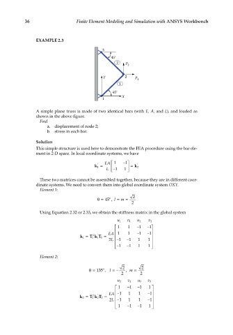
EXAMPLE 2.3
3
45°
2 P 2
Y 2 P 1
1
45°
X
1
A simple plane truss is made of two identical bars (with E, A, and L), and loaded as
shown in the above figure.
Find
a. displacement of node 2;
b. stress in each bar.
Solution
This simple structure is used here to demonstrate the FEA procedure using the bar ele-
ment in 2-D space. In local coordinate systems, we have
EA 1 − 1
′
k 1 = = k 2 ′
L − 1 1
These two matrices cannot be assembled together, because they are in different coor-
dinate systems. We need to convert them into global coordinate system OXY.
Element 1:
o
θ= 45 , l = m = 2
2
Using Equation 2.32 or 2.33, we obtain the stiffness matrix in the global system
u 1 v 1 u 2 v 2
1 1 − 1 − 1
EA 1 1 − 1 − 1
′
T
1 k = 1 T kT =
11
2 L − 1 − 1 1 1
1 − 1 1
− 1
Element 2:
2 2
o
θ= 135 , l =− , m =
2 2
u 2 v 2 u 3 v 3
1 − 1 − 1 1
EA − 1 1 1 − 1
T
′
2 k = 2 T kT =
2
2
2 L − 1 1 1 − 1
− −
1 1 1 1 