
Page 46 - Finite Element Modeling and Simulations with ANSYS Workbench
P. 46
Bars and Trusses 31
The structure stiffness matrix is assembled by using the element stiffness matrices in the
usual way as in the 1-D case.
2.4.4.2 3-D Case
Local Global
x, y, z X, Y, Z
′ i ,
i , ′ uv w i ′ u i , v i , w i
1 DOF at each node 3 DOFs at each node
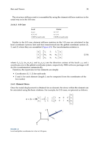
Similar to the 2-D case, element stiffness matrices in the 3-D case are calculated in the
local coordinate systems first and then transformed into the global coordinate system (X,
Y, and Z) where they are assembled (Figure 2.9). The transformation relation is
u i ′ l X l Y l Z u i
′
v i = m X m Y m Z v i (2.34)
′
w i n X n Y n Z w i
where (l ,l ,l ), (m ,m ,m ), and (n ,n ,n ) are the direction cosines of the local x, y, and z
Z
Y
Z
X
Y
X
X Y Z
coordinate axis in the global coordinate system, respectively. FEM software packages will
do this transformation automatically.
Therefore, the input data for bar elements are simply:
• Coordinates (X, Y, Z) for each node
• E and A for each element (length L can be computed from the coordinates of the
two nodes)
2.4.5 Element Stress
Once the nodal displacement is obtained for an element, the stress within the element can
be calculated using the basic relations. For example, for 2-D cases, we proceed as follows:
u i
′
1 1 l m 0 0
v i
u i
σ= E ε= EB = E −
′
L L 0 0 l m
u j
u j
v j
y
x j
Y
i
z
X
Z
FIGURE 2.9
Local and global coordinates for a bar in 3-D space.