Page 49 - Finite Element Modeling and Simulations with ANSYS Workbench
P. 49

34                    Finite Element Modeling and Simulation with ANSYS Workbench


                  Check the results:  Draw the FBD as follows and check the equilibrium of the
                 structures.

                                     –2P/3          P         –P/3


                 Notes:
                   •  In this case, the calculated stresses in elements 1 and 2 are exact. It will not
                     help if we further divide element 1 or 2 into smaller elements.
                   •  For tapered bars, averaged values of the cross-sectional areas should be used
                     for the elements.
                   •  We need to find the displacements first in order to find the stresses, and this
                     approach is called the displacement-based FEM.
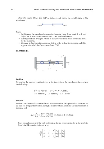
                 EXAMPLE 2.2


                                                A, E
                                         1              2
                                     1          2   P        3     x

                                          L            L


                 Problem
                 Determine the support reaction forces at the two ends of the bar shown above, given
                 the following:


                                                           4
                                            4
                                                     .
                                      .
                                  P = 60  × 10 N ,  E = 20  × 10 N/mm 2 ,
                                  A = 250 mm 2 ,  L = 150 mm,  ∆  = 1.2 mm

                 Solution
                 We first check to see if contact of the bar with the wall on the right will occur or not. To
                 do this, we imagine the wall on the right is removed and calculate the displacement at
                 the right end


                                               4
                                         60 ×
                                   PL   (.   10 )( 150)
                               ∆ 0 =  =        4     =  18 . mm  >  ∆ = . mm
                                                                  12
                                         20 ×
                                   EA   (.   10 )( 250)
                  Thus, contact occurs and the wall on the right should be accounted for in the analysis.
                  The global FE equation is found to be
                                            1  − 1  0  u 1    F 1 
                                                             
                                                         
                                                     
                                       EA  − 1  2  − 1  u 2 =  
                                                             F 2
                                        L                 
                                            0  − 1  1   u 3    F 3 
   44   45   46   47   48   49   50   51   52   53   54