
Page 122 - Fluid Mechanics and Thermodynamics of Turbomachinery
P. 122
Axial-flow Turbines: Two-dimensional Theory 103
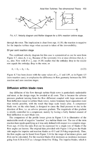
FIG. 4.7. Velocity diagram and Mollier diagram for a 50% reaction turbine stage.
through the rotor. The implication is clear from eqn. (4.18); the reaction is negative
for the impulse turbine stage when account is taken of the irreversibility.
50 per cent reaction stage
The combined velocity diagram for this case is symmetrical as can be seen from
Figure 4.7, since ˇ 3 D ˛ 2 . Because of the symmetry it is at once obvious that ˇ 2 D
1
˛ 3 , also. Now with R D , eqn. (4.18) implies that the enthalpy drop in the nozzle
2
row equals the enthalpy drop in the rotor, or
h 3 . (4.23)
h 1 h 2 D h 2
Figure 4.7 has been drawn with the same values of c x , U and W, as in Figure 4.5
(zero reaction case), to emphasise the difference in flow geometry between the 50%
reaction and zero reaction stages.
Diffusion within blade rows
Any diffusion of the flow through turbine blade rows is particularly undesirable
and must, at the design stage, be avoided at all costs. This is because the adverse
pressure gradient (arising from the flow diffusion) coupled with large amounts of
fluid deflection (usual in turbine blade rows), makes boundary-layer separation more
than merely possible, with the result that large scale losses arise. A compressor
blade row, on the other hand, is designed to cause the fluid pressure to rise in the
direction of flow, i.e. an adverse pressure gradient. The magnitude of this gradient
is strictly controlled in a compressor, mainly by having a fairly limited amount of
fluid deflection in each blade row.
The comparison of the profile losses given in Figure 3.14 is illustrative of the
undesirable result of negative “reaction” in a turbine blade row. The use of the term
reaction here needs qualifying as it was only defined with respect to a complete stage.
From eqn. (4.22a) the ratio R/ can be expressed for a single row of blades if the
flow angles are known. The original data provided with Figure 3.14 gives the blade
inlet angles for impulse and reaction blades as 45.5 and 18.9 deg respectively. Thus,
the flow angles can be found from Figure 3.14 for the range of incidence given, and
R/ can be calculated. For the reaction blades R/ decreases as incidence increases
going from 0.36 to 0.25 as i changes from 0 to 10 deg. The impulse blades, which it