
Page 123 - Fluid Mechanics and Thermodynamics of Turbomachinery
P. 123
104 Fluid Mechanics, Thermodynamics of Turbomachinery
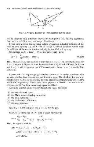
FIG. 4.8. Velocity diagram for 100% reaction turbine stage.
will be observed have a dramatic increase in blade profile loss, has R/ decreasing
from zero to 0.25 in the same range of incidence.
It was shown above that negative values of reaction indicated diffusion of the
rotor relative velocity (i.e. for R< 0, w 3 <w 2 ). A similar condition which holds
for diffusion of the nozzle absolute velocity is, that if R> 1, c 2 <c 1 .
Substituting tan ˇ 3 D tan ˛ 3 C U/c x into eqn. (4.22b) gives
c x
R D 1 C .tan ˛ 3 tan ˛ 2 /. (4.22c)
2U
Thus, when ˛ 3 D ˛ 2 , the reaction is unity (also c 2 D c 3 ). The velocity diagram for
R D 1 is shown in Figure 4.8 with the same values of c x , U and W used for R D 0
1
and R D . It will be apparent that if R exceeds unity, then c 2 <c 1 (i.e. nozzle flow
2
diffusion).
EXAMPLE 4.2. A single-stage gas turbine operates at its design condition with
an axial absolute flow at entry and exit from the stage. The absolute flow angle at
nozzle exit is 70 deg. At stage entry the total pressure and temperature are 311 kPa
and 850 ° C respectively. The exhaust static pressure is 100 kPa, the total-to-static
efficiency is 0.87 and the mean blade speed is 500 m/s.
Assuming constant axial velocity through the stage, determine
(i) the specific work done;
(ii) the Mach number leaving the nozzle;
(iii) the axial velocity;
(iv) the total-to-total efficiency;
(v) the stage reaction.
Take C p D 1.148 kJ/(kg ° C) and
D 1.33 for the gas.
Solution. (i) From eqn. (4.10), total-to-static efficiency is
W
h 01 h 03
ts D D .
1//
.
h 01 h 3ss h 01 f1 .p 3 /p 01 / g
Thus, the specific work is
W D ts C p T 01 f1 .p 3 /p 01 / .
1//
g
D 0.87 ð 1148 ð 1123 ðf1 .1/3.11/ 0.248 g
D 276 kJ/kg.