
Page 135 - Fluid Mechanics and Thermodynamics of Turbomachinery
P. 135
116 Fluid Mechanics, Thermodynamics of Turbomachinery
For blades with a constant cross-sectional area, we get
" #
Z 2 2
r t
c 2 U t r h
D r dr D 1 . (4.30a)
m 2 r t
r h
A rotor blade is usually tapered both in chord and in thickness from root to tip
such that the area ratio A t /A h is between 1/3 and 1/4. For such a blade taper it is
often assumed that the blade stress is reduced to 2/3 of the value obtained for an
untapered blade. A blade stress taper factor can be defined as:
stress at root of tapered blade
K D
stress at root of untapered blade
Thus, for tapered blades
" 2 #
KU 2
c t r h
D 1 . (4.30b)
m 2 r t
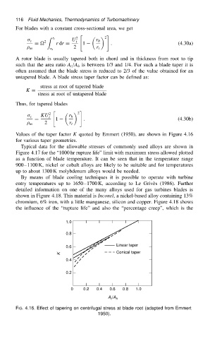
Values of the taper factor K quoted by Emmert (1950), are shown in Figure 4.16
for various taper geometries.
Typical data for the allowable stresses of commonly used alloys are shown in
Figure 4.17 for the “1000 hr rupture life” limit with maximum stress allowed plotted
as a function of blade temperature. It can be seen that in the temperature range
900 1100 K, nickel or cobalt alloys are likely to be suitable and for temperatures
up to about 1300 K molybdenum alloys would be needed.
By means of blade cooling techniques it is possible to operate with turbine
entry temperatures up to 1650 1700 K, according to Le Griv` es (1986). Further
detailed information on one of the many alloys used for gas turbines blades is
shown in Figure 4.18. This material is Inconel, a nickel-based alloy containing 13%
chromium, 6% iron, with a little manganese, silicon and copper. Figure 4.18 shows
the influence of the “rupture life” and also the “percentage creep”, which is the
1.0
0.8
Linear taper
0.6
K Conical taper
0.4
0.2
0 0.2 0.4 0.6 0.8 1.0
A /A h
t
FIG. 4.16. Effect of tapering on centrifugal stress at blade root (adapted from Emmert
1950).