
Page 140 - Fluid Mechanics and Thermodynamics of Turbomachinery
P. 140
Axial-flow Turbines: Two-dimensional Theory 121
FIG. 4.19. Cooled HP turbine rotor blade showing the cooling passages (courtesy of
Rolls-Royce plc).
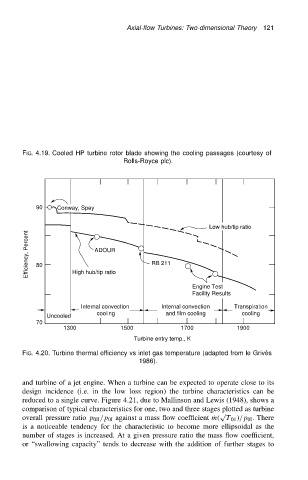
90 Conway, Spey
Low hub/tip ratio
Efficiency, Percent 80 ADOUR RB 211
High hub/tip ratio
Engine Test
Facility Results
Internal convection Internal convection Transpiration
cooling and film cooling cooling
Uncooled
70
1300 1500 1700 1900
Turbine entry temp., K
FIG. 4.20. Turbine thermal efficiency vs inlet gas temperature (adapted from le Griv` es
1986).
and turbine of a jet engine. When a turbine can be expected to operate close to its
design incidence (i.e. in the low loss region) the turbine characteristics can be
reduced to a single curve. Figure 4.21, due to Mallinson and Lewis (1948), shows a
comparison of typical characteristics for one, two and three stages plotted as turbine
p
overall pressure ratio p 0II /p 0I against a mass flow coefficient Pm. T 01 //p 0I . There
is a noticeable tendency for the characteristic to become more ellipsoidal as the
number of stages is increased. At a given pressure ratio the mass flow coefficient,
or “swallowing capacity” tends to decrease with the addition of further stages to