
Page 141 - Fluid Mechanics and Thermodynamics of Turbomachinery
P. 141
122 Fluid Mechanics, Thermodynamics of Turbomachinery
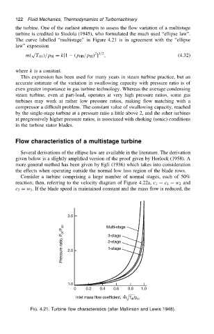
the turbine. One of the earliest attempts to assess the flow variation of a multistage
turbine is credited to Stodola (1945), who formulated the much used “ellipse law”.
The curve labelled “multistage” in Figure 4.21 is in agreement with the “ellipse
law” expression
p 2 1/2
m. T 01 //p 0I D k[1 .p 0II /p 0I / ] , (4.32)
where k is a constant.
This expression has been used for many years in steam turbine practice, but an
accurate estimate of the variation in swallowing capacity with pressure ratio is of
even greater importance in gas turbine technology. Whereas the average condensing
steam turbine, even at part-load, operates at very high pressure ratios, some gas
turbines may work at rather low pressure ratios, making flow matching with a
compressor a difficult problem. The constant value of swallowing capacity, reached
by the single-stage turbine at a pressure ratio a little above 2, and the other turbines
at progressively higher pressure ratios, is associated with choking (sonic) conditions
in the turbine stator blades.
Flow characteristics of a multistage turbine
Several derivations of the ellipse law are available in the literature. The derivation
given below is a slightly amplified version of the proof given by Horlock (1958). A
more general method has been given by Egli (1936) which takes into consideration
the effects when operating outside the normal low loss region of the blade rows.
Consider a turbine comprising a large number of normal stages, each of 50%
reaction; then, referring to the velocity diagram of Figure 4.22a, c 1 D c 3 D w 2 and
c 2 D w 3 . If the blade speed is maintained constant and the mass flow is reduced, the
FIG. 4.21. Turbine flow characteristics (after Mallinson and Lewis 1948).