
Page 142 - Fluid Mechanics and Thermodynamics of Turbomachinery
P. 142
Axial-flow Turbines: Two-dimensional Theory 123
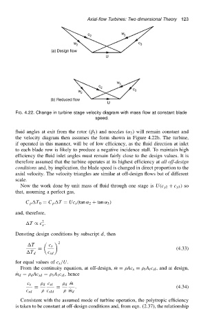
FIG. 4.22. Change in turbine stage velocity diagram with mass flow at constant blade
speed.
fluid angles at exit from the rotor (ˇ 3 ) and nozzles (˛ 2 ) will remain constant and
the velocity diagram then assumes the form shown in Figure 4.22b. The turbine,
if operated in this manner, will be of low efficiency, as the fluid direction at inlet
to each blade row is likely to produce a negative incidence stall. To maintain high
efficiency the fluid inlet angles must remain fairly close to the design values. It is
therefore assumed that the turbine operates at its highest efficiency at all off-design
conditions and, by implication, the blade speed is changed in direct proportion to the
axial velocity. The velocity triangles are similar at off-design flows but of different
scale.
Now the work done by unit mass of fluid through one stage is U.c y2 C c y3 / so
that, assuming a perfect gas,
C p T 0 D C p T D Uc x .tan ˛ 2 C tan ˛ 3 /
and, therefore,
2
T / c .
x
Denoting design conditions by subscript d, then
2
T c x
D (4.33)
T d c xd
for equal values of c x /U.
From the continuity equation, at off-design, Pm D Ac x D I A I c xI , and at design,
P m d D d Ac xd D 1 A 1 c xI , hence
d Pm
c x d c xI
D D . (4.34)
c xd c xId Pm d
Consistent with the assumed mode of turbine operation, the polytropic efficiency
is taken to be constant at off-design conditions and, from eqn. (2.37), the relationship