
Page 145 - Fluid Mechanics and Thermodynamics of Turbomachinery
P. 145
126 Fluid Mechanics, Thermodynamics of Turbomachinery
Electrical
generator
Turbo generator
shaft
Oscillating
air flow
Tube
Wells turbine
(rotor hub)
Uni-
directional Uncambered aerofoils
rotation at 90 deg stagger angle
(i.e. chord lines lie in
plane of rotation)
Oscillating
air flow
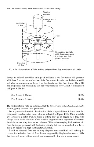
FIG. 4.24. Schematic of a Wells turbine (adapted from Raghunathan et al. 1995).
theory, an isolated aerofoil at an angle of incidence ˛ to a free stream will generate
a lift force L normal to the direction of the free stream. In a viscous fluid the aerofoil
will also experience a drag force D in the direction of the free stream. These lift
and drag forces can be resolved into the components of force X and Y as indicated
in Figure 4.25a, i.e.
X D L cos ˛ C D sin ˛, .4.39/
Y D L sin ˛ D cos ˛. .4.40/
The student should note, in particular, that the force Y acts in the direction of blade
motion, giving positive work production.
For a symmetrical aerofoil, the direction of the tangential force Y is the same for
both positive and negative values of ˛, as indicated in Figure 4.25b. If the aerofoils
are secured to a rotor drum to form a turbine row, as in Figure 4.24, they will
always rotate in the direction of the positive tangential force regardless of whether
the air is approaching from above or below. With a time-varying, bi-directional air
flow the torque produced will fluctuate cyclically but can be smoothed to a large
extent by means of a high inertia rotor/generator.
It will be observed from the velocity diagrams that a residual swirl velocity is
present for both directions of flow. It was suggested by Raghunathan et al. (1995)
that the swirl losses at turbine exit can be reduced by the use of guide vanes.