
Page 402 - Fluid-Structure Interactions Slender Structure and Axial Flow (Volume 1)
P. 402
378 SLENDER STRUCTURES AND AXIAL, FLOW
.e '.
5.-- -
1 0.10 ; I'\ !
\
6 -... A
I
0.05 - -. ->> .\;? I -
,v\-- .-.-.-. -.-
..
.. .-/ \J
..
.. , , , ,
. .
0.00 ""I ., ,. , , , , , , , , , , , , , ,
0.4
0.3
0.2
0.1
0.0
4 5 6 7 8 9 10 11
(b) Velocity, u
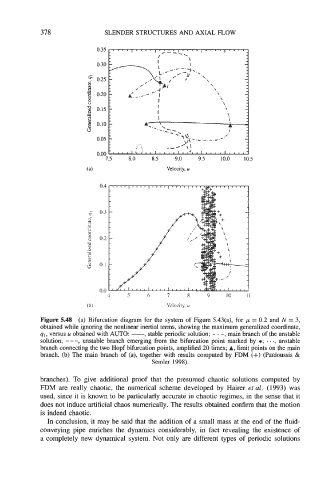
Figure 5.48 (a) Bifurcation diagram for the system of Figure 5.43(a), for p = 0.2 and N = 3,
obtained while ignoring the nonlinear inertial terms, showing the maximum generalized coordinate,
91, versus u obtained with AUTO: -, stable periodic solution; - . -, main branch of the unstable
solution; - - -, unstable branch emerging from the bifurcation point marked by a; . . ., unstable
branch connecting the two Hopf bifurcation points, amplified 20 times; A, limit points on the main
branch. (b) The main branch of (a), together with results computed by FDM (+) (Pdidoussis &
Semler 1998).
branches). To give additional proof that the presumed chaotic solutions computed by
FDM are really chaotic, the numerical scheme developed by Hairer et al. (1993) was
used, since it is known to be particularly accurate in chaotic regimes, in the sense that it
does not induce artificial chaos numerically. The results obtained confirm that the motion
is indeed chaotic.
In conclusion, it may be said that the addition of a small mass at the end of the fluid-
conveying pipe enriches the dynamics considerably, in fact revealing the existence of
a completely new dynamical system. Not only are different types of periodic solutions