
Page 205 - Fluid mechanics, heat transfer, and mass transfer
P. 205
MIXING EQUIPMENT 183
Helical coil and anchor mixers.
FIGURE 6.14
& Anchor impellers are used for an intermediate range 6.2.6.1 Static Mixers
of 0.5 > N Re > 10, because they are much less ex-
pensivethan helical ribbons and they sweep the entire . What are static mixers? Give examples.
vessel volume, whereas a turbine leaves stagnant
& Static mixing involves homogenization without
areas near the vessel walls for N Re < 10.
using moving parts. In contrast to dynamic mixing,
. “For high-viscosity liquids propeller mixers are better
suited than turbine mixers.” True/False?
& False.
. What type of mixer is used for very high-viscosity
applications (40,000–50,000 cP)?
& Anchor type.
. “Slow speed close clearance impellers (helical coil or
anchor type) are used when mixing high-viscosity
liquids.” True/False?
& True.
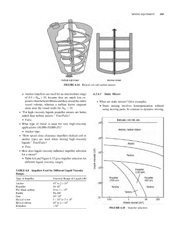
. How does liquid viscosity influence impeller selection
for a mixer?
& Table 6.8 and Figure 6.15 give impeller selection for
different liquid viscosity ranges.
TABLE 6.8 Impellers Used for Different Liquid Viscosity
Ranges
Type of Impeller Viscosity Range of Liquid (cP)
2
Anchor 10 to 2 10 3
Propeller 10–10 4
Flat blade turbine 10 to 3 10 4
Paddle 30–100
3
Gate 10 –10 5
3
Helical screw 3 10 to 3 10 5
4
Helical ribbon 10 to 2 10 3
Extruders >10 6
FIGURE 6.15 Impeller selection.