
Page 332 - T. Anderson-Fracture Mechanics - Fundamentals and Applns.-CRC (2005)
P. 332
1656_C007.fm Page 312 Monday, May 23, 2005 5:54 PM
312 Fracture Mechanics: Fundamentals and Applications
Solution: For the L-T or T-L orientation, a test specimen with a standard design could be no larger than
B = a = 25 mm and W = 50 mm. Inserting these dimensions and the yield strength into Equation (7.2a)
and solving for K Ic gives
K = Ic 0.025 m = 350 MPa 35 MPa m
.
25
Figure 4.5 shows fracture toughness data for A 572 Grade 50 steel. Note that the toughness level computed
above corresponds to the lower shelf in this material. Thus, valid K Ic tests on this material would be
possible only at low temperatures, where the material is too brittle for most structural applications.
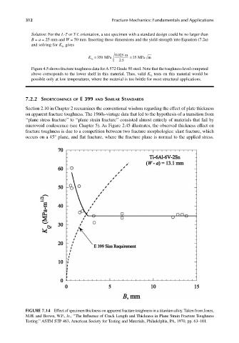
7.2.2 SHORTCOMINGS OF E 399 AND SIMILAR STANDARDS
Section 2.10 in Chapter 2 reexamines the conventional wisdom regarding the effect of plate thickness
on apparent fracture toughness. The 1960s-vintage data that led to the hypothesis of a transition from
‘‘plane stress fracture’’ to ‘‘plane strain fracture’’ consisted almost entirely of materials that fail by
microvoid coalescence (see Chapter 5). As Figure 2.45 illustrates, the observed thickness effect on
fracture toughness is due to a competition between two fracture morphologies: slant fracture, which
occurs on a 45° plane, and flat fracture, where the fracture plane is normal to the applied stress.
FIGURE 7.14 Effect of specimen thickness on apparent fracture toughness in a titanium alloy. Taken from Jones,
M.H. and Brown, W.F., Jr., ‘‘The Influence of Crack Length and Thickness in Plane Strain Fracture Toughness
Testing.’’ ASTM STP 463, American Society for Testing and Materials, Philadelphia, PA, 1970, pp. 63–101.