
Page 337 - T. Anderson-Fracture Mechanics - Fundamentals and Applns.-CRC (2005)
P. 337
1656_C007.fm Page 317 Monday, May 23, 2005 5:54 PM
Fracture Toughness Testing of Metals 317
governed by the size and geometry of the cracked body. In a laboratory specimen under load control,
for example, K would correspond to P max in a Type I load-displacement curve (Figure 7.13). Such
c
a K value would exhibit a size dependence similar to that observed for K based on a 2% crack
c
Q
growth criterion, as Figure 7.17 illustrates. Consequently, K values obtained from laboratory
c
specimens are not usually transferable to structures.
7.3.1 SPECIMEN DESIGN
The ASTM standard for K-R curve testing [14] permits three configurations of test specimens: the
middle tension (MT) geometry, the conventional compact specimen, and a wedge-loaded compact
specimen. The latter configuration, which is similar to the compact crack-arrest specimen discussed
in Section 7.6, is the most stable of the three specimen types, and thus is suitable for materials
with relatively flat R curves.
Since this test method is often applied to thin sheets, specimens do not usually have the
conventional geometry, with the width equal to twice the thickness. The specimen thickness is
normally fixed by the sheet thickness, and the width is governed by the anticipated toughness of
the material, as well as the available test fixtures.
A modified nomenclature is applied to thin-sheet compact specimens. For example, a specimen
with W = 50 mm (2 in.) is designated as a 1T plan specimen, since the in-plane dimensions correspond
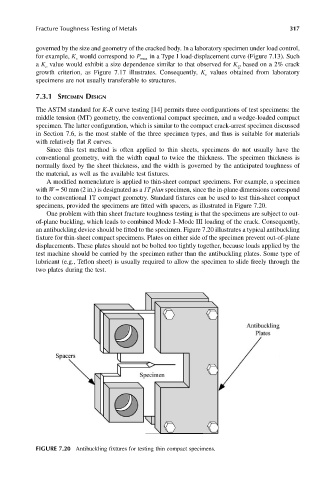
to the conventional 1T compact geometry. Standard fixtures can be used to test thin-sheet compact
specimens, provided the specimens are fitted with spacers, as illustrated in Figure 7.20.
One problem with thin sheet fracture toughness testing is that the specimens are subject to out-
of-plane buckling, which leads to combined Mode I–Mode III loading of the crack. Consequently,
an antibuckling device should be fitted to the specimen. Figure 7.20 illustrates a typical antibuckling
fixture for thin-sheet compact specimens. Plates on either side of the specimen prevent out-of-plane
displacements. These plates should not be bolted too tightly together, because loads applied by the
test machine should be carried by the specimen rather than the antibuckling plates. Some type of
lubricant (e.g., Teflon sheet) is usually required to allow the specimen to slide freely through the
two plates during the test.
FIGURE 7.20 Antibuckling fixtures for testing thin compact specimens.