
Page 339 - T. Anderson-Fracture Mechanics - Fundamentals and Applns.-CRC (2005)
P. 339
1656_C007.fm Page 319 Monday, May 23, 2005 5:54 PM
Fracture Toughness Testing of Metals 319
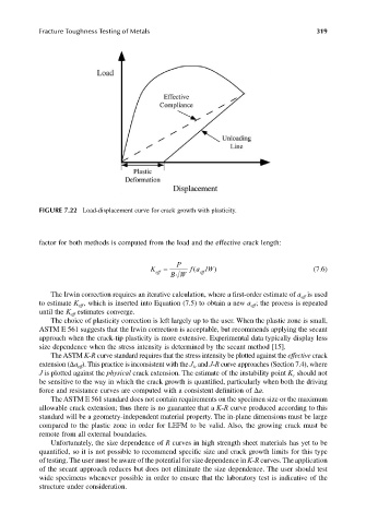
FIGURE 7.22 Load-displacement curve for crack growth with plasticity.
factor for both methods is computed from the load and the effective crack length:
P
K eff = BW fa / W) (7.6)
(
eff
The Irwin correction requires an iterative calculation, where a first-order estimate of a is used
eff
to estimate K , which is inserted into Equation (7.5) to obtain a new a ; the process is repeated
eff
eff
until the K estimates converge.
eff
The choice of plasticity correction is left largely up to the user. When the plastic zone is small,
ASTM E 561 suggests that the Irwin correction is acceptable, but recommends applying the secant
approach when the crack-tip plasticity is more extensive. Experimental data typically display less
size dependence when the stress intensity is determined by the secant method [15].
The ASTM K-R curve standard requires that the stress intensity be plotted against the effective crack
extension (∆a ). This practice is inconsistent with the J and J-R curve approaches (Section 7.4), where
eff
Ic
J is plotted against the physical crack extension. The estimate of the instability point K should not
c
be sensitive to the way in which the crack growth is quantified, particularly when both the driving
force and resistance curves are computed with a consistent definition of ∆a.
The ASTM E 561 standard does not contain requirements on the specimen size or the maximum
allowable crack extension; thus there is no guarantee that a K-R curve produced according to this
standard will be a geometry-independent material property. The in-plane dimensions must be large
compared to the plastic zone in order for LEFM to be valid. Also, the growing crack must be
remote from all external boundaries.
Unfortunately, the size dependence of R curves in high strength sheet materials has yet to be
quantified, so it is not possible to recommend specific size and crack growth limits for this type
of testing. The user must be aware of the potential for size dependence in K-R curves. The application
of the secant approach reduces but does not eliminate the size dependence. The user should test
wide specimens whenever possible in order to ensure that the laboratory test is indicative of the
structure under consideration.