Page 341 - T. Anderson-Fracture Mechanics - Fundamentals and Applns.-CRC (2005)
P. 341

1656_C007.fm  Page 321  Monday, May 23, 2005  5:54 PM


                       Fracture Toughness Testing of Metals                                        321


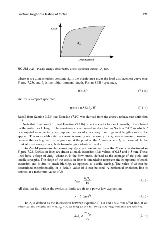
                       FIGURE 7.23  Plastic energy absorbed by a test specimen during a J Ic  test.


                       where h is a dimensionless constant, A  is the plastic area under the load-displacement curve (see
                                                      pl
                       Figure 7.23), and b  is the initial ligament length. For an SE(B) specimen,
                                      o
                                                                .
                                                           η = 20                               (7.11a)
                       and for a compact specimen,

                                                      η =+ 0 522 bW                             (7.11b)
                                                              .
                                                                    /
                                                          2
                                                                   o
                       Recall from Section 3.2.5 that Equation (7.10) was derived from the energy release rate definition
                       of J.
                          Note that Equation (7.10) and Equation (7.11b) do not correct J for crack growth, but are based
                       on the initial crack length. The resistance curve procedure described in Section 7.4.2, in which J
                       is computed incrementally with updated values of crack length and ligament length, can also be
                       applied. This more elaborate procedure is usually not necessary for J  measurements, however,
                                                                                Ic
                       because the crack growth is insignificant at the point on the R curve where J  is measured. In the
                                                                                     Ic
                       limit of a stationary crack, both formulas give identical results.
                          The ASTM procedure for computing J , a provisional J , from the R curve is illustrated in
                                                          Q
                                                                        Ic
                       Figure 7.24. Exclusion lines are drawn at crack extension (∆a) values of 0.15 and 1.5 mm. These
                       lines have a slope of Mσ , where σ  is the flow stress, defined as the average of the yield and
                                            Y
                                                     Y
                       tensile strengths. The slope of the exclusion lines is intended to represent the component of crack
                       extension that is due to crack blunting, as opposed to ductile tearing.  The value of  M can be
                       determined experimentally, or a default value of 2 can be used. A horizontal exclusion line is
                       defined at a maximum value of J:
                                                               b σ
                                                         J   =  o  Y                             (7.12)
                                                          max
                                                                15
                       All data that fall within the exclusion limits are fit to a power-law expression:
                                                         J  C =  a(∆  ) C 2                      (7.13)
                                                              1
                          The J  is defined as the intersection between Equation (7.13) and a 0.2-mm offset line. If all
                              Q
                       other validity criteria are met, J  = J  as long as the following size requirements are satisfied:
                                                     Ic
                                                Q
                                                               25 J
                                                         Bb ≥   σ Y Q                            (7.14)
                                                          ,
                                                            o
   336   337   338   339   340   341   342   343   344   345   346