
Page 343 - T. Anderson-Fracture Mechanics - Fundamentals and Applns.-CRC (2005)
P. 343
1656_C007.fm Page 323 Monday, May 23, 2005 5:54 PM
Fracture Toughness Testing of Metals 323
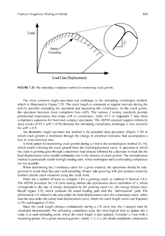
FIGURE 7.25 The unloading compliance method for monitoring crack growth.
The most common single-specimen test technique is the unloading compliance method,
which is illustrated in Figure 7.25. The crack length is computed at regular intervals during the
test by partially unloading the specimen and measuring the compliance. As the crack grows,
the specimen becomes more compliant (less stiff). The various J testing standards provide
polynomial expressions that relate a/W to compliance. Table A7.3 in Appendix 7 lists these
compliance equations for bend and compact specimens. The ASTM standard requires relatively
deep cracks (0.50 ≤ a/W < 0.70) because the unloading compliance technique is less sensitive
for a/W < 0.5.
An alternative single-specimen test method is the potential drop procedure (Figure 7.10) in
which crack growth is monitored through the change in electrical resistance that accompanies a
loss in cross-sectional area.
A third option for monitoring crack growth during a J test is the normalization method [4, 16],
which entails inferring the crack growth from the load-displacement curve. A specimen in which
the crack is growing goes through a maximum load plateau followed by a decrease in load, but the
load-displacement curve would continually rise in the absence of crack growth. The normalization
method is particularly useful for high loading rates, where techniques such as unloading compliance
are not possible.
When determining the J resistance curve for a given material, the specimens should be side-
grooved to avoid shear lips and crack tunneling. Proper side-grooving will also produce relatively
uniform ductile crack extension along the crack front.
There are a number of ways to compute J for a growing crack, as outlined in Section 3.4.2.
The ASTM procedure for J-R curve testing utilizes the deformation theory definition of J, which
corresponds to the rate of energy dissipation by the growing crack (i.e., the energy release rate).
Recall Figure 3.22, which contrasts the actual loading path with the ‘‘deformation’’ path. The
deformation J is related to the area under the load-displacement curve for a stationary crack, rather
than the area under the actual load-displacement curve, where the crack length varies (see Equation
(3.55) and Equation (3.56)).
Since the crack length changes continuously during a J-R curve test, the J integral must be
calculated incrementally. For unloading compliance tests, the most logical time to update the J
value is at each unloading point, where the crack length is also updated. Consider a J test with n
measuring points. For a given measuring point i, where 1 ≤≤ n i , the elastic and plastic components