
Page 342 - T. Anderson-Fracture Mechanics - Fundamentals and Applns.-CRC (2005)
P. 342
1656_C007.fm Page 322 Monday, May 23, 2005 5:54 PM
322 Fracture Mechanics: Fundamentals and Applications
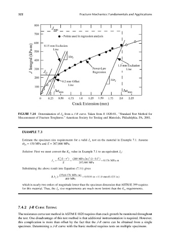
FIGURE 7.24 Determination of J Q from a J-R curve. Taken from E 1820-01, ‘‘Standard Test Method for
Measurement of Fracture Toughness.’’ American Society for Testing and Materials, Philadelphia, PA, 2001.
EXAMPLE 7.3
Estimate the specimen size requirements for a valid J Ic test on the material in Example 7.1. Assume
σ TS = 450 MPa and E = 207,000 MPa.
Solution: First we must convert the K Ic value in Example 7.1 to an equivalent J Ic :
2
2
J = K 1( E −ν 2 ) = ( 200 MPa m ) 2 1 ( − 0 3. ) = 0 176. MPa-m
Ic
Ic
,
207 000 MPa
Substituting the above result into Equation (7.14) gives
25
Bb ≥ , o ()(0.176 MPa-m ) = . 0 0110 m = 11 .0 mm ( .433 in. )
0
400 MPa
which is nearly two orders of magnitude lower than the specimen dimension that ASTM E 399 requires
for this material. Thus, the J Ic size requirements are much more lenient than the K Ic requirements.
7.4.2 J-R CURVE TESTING
The resistance curve test method in ASTM E 1820 requires that crack growth be monitored throughout
the test. One disadvantage of this test method is that additional instrumentation is required. However,
this complication is more than offset by the fact that the J-R curve can be obtained from a single
specimen. Determining a J-R curve with the basic method requires tests on multiple specimens.