
Page 338 - T. Anderson-Fracture Mechanics - Fundamentals and Applns.-CRC (2005)
P. 338
1656_C007.fm Page 318 Monday, May 23, 2005 5:54 PM
318 Fracture Mechanics: Fundamentals and Applications
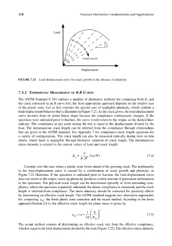
FIGURE 7.21 Load-displacement curve for crack growth in the absence of plasticity.
7.3.2 EXPERIMENTAL MEASUREMENT OF K-R CURVES
The ASTM Standard E 561 outlines a number of alternative methods for computing both K and
I
the crack extension in an R curve test; the most appropriate approach depends on the relative size
of the plastic zone. Let us first consider the special case of negligible plasticity, which exhibits a
load-displacement behavior that is illustrated in Figure 7.21. As the crack grows, the load-displacement
curve deviates from its initial linear shape because the compliance continuously changes. If the
specimen were unloaded prior to fracture, the curve would return to the origin, as the dashed lines
indicate. The compliance at any point during the test is equal to the displacement divided by the
load. The instantaneous crack length can be inferred from the compliance through relationships
that are given in the ASTM standard. See Appendix 7 for compliance-crack length equations for
a variety of configurations. The crack length can also be measured optically during tests on thin
sheets, where there is negligible through-thickness variation of crack length. The instantaneous
stress intensity is related to the current values of load and crack length:
P
K = BW fa W) (7.4)
/
(
I
Consider now the case where a plastic zone forms ahead of the growing crack. The nonlinearity
in the load-displacement curve is caused by a combination of crack growth and plasticity, as
Figure 7.22 illustrates. If the specimen is unloaded prior to fracture, the load-displacement curve
does not return to the origin; crack-tip plasticity produces a finite amount of permanent deformation
in the specimen. The physical crack length can be determined optically or from unloading com-
pliance, where the specimen is partially unloaded, the elastic compliance is measured, and the crack
length is inferred from compliance. The stress intensity should be corrected for plasticity effects
by determining an effective crack length. The ASTM standard suggests two alternative approaches
for computing a : the Irwin plastic zone correction and the secant method. According to the Irwin
eff
approach (Section 2.8.1), the effective crack length for plane stress is given by
1
a eff =+ 2πσ K 2 (7.5)
a
YS
The secant method consists of determining an effective crack size from the effective compliance,
which is equal to the total displacement divided by the load (Figure 7.22). The effective stress-intensity