
Page 344 - T. Anderson-Fracture Mechanics - Fundamentals and Applns.-CRC (2005)
P. 344
1656_C007.fm Page 324 Monday, May 23, 2005 5:54 PM
324 Fracture Mechanics: Fundamentals and Applications
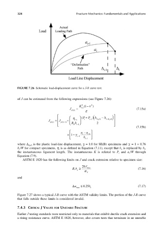
FIGURE 7.26 Schematic load-displacement curve for a J-R curve test.
of J can be estimated from the following expressions (see Figure 7.26):
K ( −1 ν 2 )
2
J = i () (7.15a)
el i() E
P ( + P )( η − ∆ pl)) ∆
(
J = J ) i−1 i i −1 ipl) i−1 (
+
pl i () pl i ( −1 Bb 2
Ni−1
(7.15b)
a a −
× − 1 γ i i −1
i−1 b i−1
where ∆ i(pl) is the plastic load-line displacement, γ = 1.0 for SE(B) specimens and γ = 1 + 0.76
i
i
b /W for compact specimens, η is as defined in Equation (7.11), except that b is replaced by b , i
o
i
i
the instantaneous ligament length. The instantaneous K is related to P and a /W through
i
i
Equation (7.9).
ASTM E 1820 has the following limits on J and crack extension relative to specimen size:
20 J
Bb ≥ σ Y max (7.16)
,
o
and
∆ a ≤ . 025 b (7.17)
max o
Figure 7.27 shows a typical J-R curve with the ASTM validity limits. The portion of the J-R curve
that falls outside these limits is considered invalid.
7.4.3 CRITICAL J VALUES FOR UNSTABLE FRACTURE
Earlier J testing standards were restricted only to materials that exhibit ductile crack extension and
a rising resistance curve. ASTM E 1820, however, also covers tests that terminate in an unstable