
Page 352 - T. Anderson-Fracture Mechanics - Fundamentals and Applns.-CRC (2005)
P. 352
1656_C007.fm Page 332 Monday, May 23, 2005 5:54 PM
332 Fracture Mechanics: Fundamentals and Applications
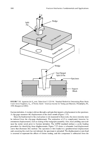
FIGURE 7.31 Apparatus for K Ia tests. Taken from E 1221-96, ‘‘Standard Method for Determining Plane-Strain
Crack-Arrest Toughness, K Ia , of Ferritic Steels.’’ American Society for Testing and Materials, Philadelphia, PA,
1996 (Reapproved 2002).
fracture initiation. A wedge is driven through a split pin that imparts a displacement to the specimen.
A clip gage measures the displacement at the crack mouth (Figure 7.33).
Since the load normal to the crack plane is not measured in these tests, the stress intensity must
be inferred from the clip-gage displacement. The estimation of K is complicated, however, by
extraneous displacements, such as seating of the wedge/pin assembly. Also, local yielding can occur
near the starter notch prior to fracture initiation. The ASTM standard outlines a cyclic loading
procedure for identifying these displacements; Figure 7.33 shows a schematic load-displacement
curve that illustrates this method. The specimen is first loaded to a predetermined displacement
and, assuming the crack has not initiated, the specimen is unloaded. The displacement at zero load
is assumed to represent the effects of fixture seating, and this component is subtracted from the