
Page 355 - T. Anderson-Fracture Mechanics - Fundamentals and Applns.-CRC (2005)
P. 355
1656_C007.fm Page 335 Monday, May 23, 2005 5:54 PM
Fracture Toughness Testing of Metals 335
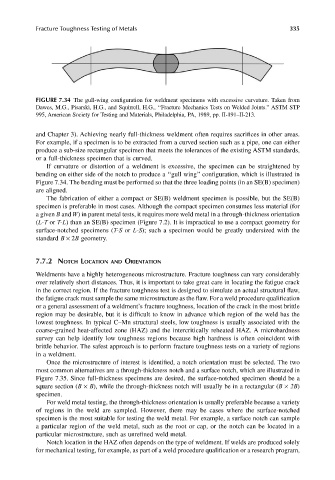
FIGURE 7.34 The gull-wing configuration for weldment specimens with excessive curvature. Taken from
Dawes, M.G., Pisarski, H.G., and Squirrell, H.G., ‘‘Fracture Mechanics Tests on Welded Joints.’’ ASTM STP
995, American Society for Testing and Materials, Philadelphia, PA, 1989, pp. II-191–II-213.
and Chapter 3). Achieving nearly full-thickness weldment often requires sacrifices in other areas.
For example, if a specimen is to be extracted from a curved section such as a pipe, one can either
produce a sub-size rectangular specimen that meets the tolerances of the existing ASTM standards,
or a full-thickness specimen that is curved.
If curvature or distortion of a weldment is excessive, the specimen can be straightened by
bending on either side of the notch to produce a ‘‘gull wing’’ configuration, which is illustrated in
Figure 7.34. The bending must be performed so that the three loading points (in an SE(B) specimen)
are aligned.
The fabrication of either a compact or SE(B) weldment specimen is possible, but the SE(B)
specimen is preferable in most cases. Although the compact specimen consumes less material (for
a given B and W) in parent metal tests, it requires more weld metal in a through-thickness orientation
(L-T or T-L) than an SE(B) specimen (Figure 7.2). It is impractical to use a compact geometry for
surface-notched specimens (T-S or L-S); such a specimen would be greatly undersized with the
standard B × 2B geometry.
7.7.2 NOTCH LOCATION AND ORIENTATION
Weldments have a highly heterogeneous microstructure. Fracture toughness can vary considerably
over relatively short distances. Thus, it is important to take great care in locating the fatigue crack
in the correct region. If the fracture toughness test is designed to simulate an actual structural flaw,
the fatigue crack must sample the same microstructure as the flaw. For a weld procedure qualification
or a general assessment of a weldment’s fracture toughness, location of the crack in the most brittle
region may be desirable, but it is difficult to know in advance which region of the weld has the
lowest toughness. In typical C–Mn structural steels, low toughness is usually associated with the
coarse-grained heat-affected zone (HAZ) and the intercritically reheated HAZ. A microhardness
survey can help identify low toughness regions because high hardness is often coincident with
brittle behavior. The safest approach is to perform fracture toughness tests on a variety of regions
in a weldment.
Once the microstructure of interest is identified, a notch orientation must be selected. The two
most common alternatives are a through-thickness notch and a surface notch, which are illustrated in
Figure 7.35. Since full-thickness specimens are desired, the surface-notched specimen should be a
square section (B × B), while the through-thickness notch will usually be in a rectangular (B × 2B)
specimen.
For weld metal testing, the through-thickness orientation is usually preferable because a variety
of regions in the weld are sampled. However, there may be cases where the surface-notched
specimen is the most suitable for testing the weld metal. For example, a surface notch can sample
a particular region of the weld metal, such as the root or cap, or the notch can be located in a
particular microstructure, such as unrefined weld metal.
Notch location in the HAZ often depends on the type of weldment. If welds are produced solely
for mechanical testing, for example, as part of a weld procedure qualification or a research program,