
Page 356 - T. Anderson-Fracture Mechanics - Fundamentals and Applns.-CRC (2005)
P. 356
1656_C007.fm Page 336 Monday, May 23, 2005 5:54 PM
336 Fracture Mechanics: Fundamentals and Applications
FIGURE 7.35 Notch orientation in weldment specimens. (a) through-thickness notch and (b) surface notch.
Taken from Dawes, M.G., Pisarski, H.G., and Squirrell, H.G., ‘‘Fracture Mechanics Tests on Welded Joints.’’
ASTM STP 995, American Society for Testing and Materials, Philadelphia, PA, 1989, pp. II-191–II-213.
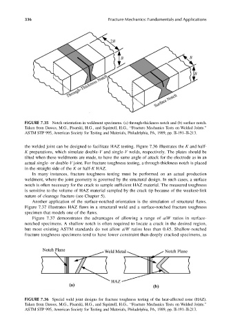
the welded joint can be designed to facilitate HAZ testing. Figure 7.36 illustrates the K and half-
K preparations, which simulate double-V and single-V welds, respectively. The plates should be
tilted when these weldments are made, to have the same angle of attack for the electrode as in an
actual single- or double-V joint. For fracture toughness testing, a through-thickness notch is placed
in the straight side of the K or half-K HAZ.
In many instances, fracture toughness testing must be performed on an actual production
weldment, where the joint geometry is governed by the structural design. In such cases, a surface
notch is often necessary for the crack to sample sufficient HAZ material. The measured toughness
is sensitive to the volume of HAZ material sampled by the crack tip because of the weakest-link
nature of cleavage fracture (see Chapter 5).
Another application of the surface-notched orientation is the simulation of structural flaws.
Figure 7.37 illustrates HAZ flaws in a structural weld and a surface-notched fracture toughness
specimen that models one of the flaws.
Figure 7.37 demonstrates the advantages of allowing a range of a/W ratios in surface-
notched specimens. A shallow notch is often required to locate a crack in the desired region,
but most existing ASTM standards do not allow a/W ratios less than 0.45. Shallow-notched
fracture toughness specimens tend to have lower constraint than deeply cracked specimens, as
FIGURE 7.36 Special weld joint designs for fracture toughness testing of the heat-affected zone (HAZ).
Taken from Dawes, M.G., Pisarski, H.G., and Squirrell, H.G., ‘‘Fracture Mechanics Tests on Welded Joints.’’
ASTM STP 995, American Society for Testing and Materials, Philadelphia, PA, 1989, pp. II-191–II-213.