
Page 285 - Fundamentals of Reservoir Engineering
P. 285
OILWELL TESTING 222
CLOCK
VERTICAL CHART
MOVEMENT ∝ TIME
STATIC PRESSURE-
DEPTH SURVEY
CHART FLOWING PRESSURE-
PRESSURE DEPTH SURVEY
(a) p ws
p wf
STYLUS
t ∆
TIME BASE LINE
STYLUS MOVEMENT (b)
∝ PRESSURE
BOURDON PRESSURE ELEMENT
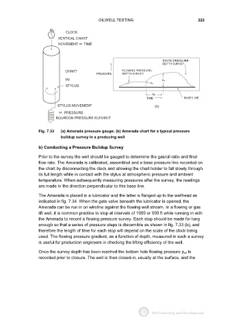
Fig. 7.33 (a) Amerada pressure gauge; (b) Amerada chart for a typical pressure
buildup survey in a producing well
b) Conducting a Pressure Buildup Survey
Prior to the survey the well should be gauged to determine the gas/oil ratio and final
flow rate. The Amerada is calibrated, assembled and a base pressure line recorded on
the chart by disconnecting the clock and allowing the chart holder to fall slowly through
its full length while in contact with the stylus at atmospheric pressure and ambient
temperature. When subsequently measuring pressures after the survey, the readings
are made in the direction perpendicular to this base line.
The Amerada is placed in a lubricator and the latter is flanged up to the wellhead as
indicated in fig. 7.34. When the gate valve beneath the lubricator is opened, the
Amerada can be run in on wireline against the flowing well stream. In a flowing or gas
lift well, it is common practice to stop at intervals of 1000 or 500 ft while running in with
the Amerada to record a flowing pressure survey. Each stop should be made for long
enough so that a series of pressure steps is discernible as shown in fig. 7.33 (b), and
therefore the length of time for each stop will depend on the scale of the clock being
used. The flowing pressure gradient, as a function of depth, measured in such a survey
is useful for production engineers in checking the lifting efficiency of the well.
Once the survey depth has been reached the bottom hole flowing pressure p wf is
recorded prior to closure. The well is then closed-in, usually at the surface, and the