Page 65 - Fundamentals of The Finite Element Method for Heat and Fluid Flow
P. 65

THE FINITE ELEMENT METHOD
                                               y
                                                       7                                       57
                                                             6
                                                    8
                                                                  5
                                                        10
                                                   9
                                                                       4
                                                                3
                                                   1     2
                                                                         x

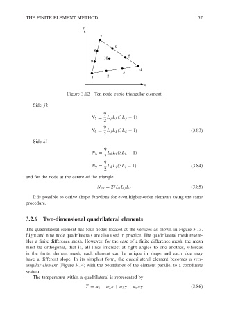
                                         Figure 3.12 Ten-node cubic triangular element

                           Side jk
                                                        9
                                                   N 5 =  L j L k (3L j − 1)
                                                        2
                                                        9
                                                   N 6 =  L j L k (3L k − 1)                (3.83)
                                                        2
                           Side ki
                                                        9
                                                   N 8 =  L k L i (3L k − 1)
                                                        2
                                                        9
                                                   N 9 =  L k L i (3L i − 1)                (3.84)
                                                        2
                        and for the node at the centre of the triangle

                                                     N 10 = 27L i L j L k                   (3.85)
                           It is possible to derive shape functions for even higher-order elements using the same
                        procedure.


                        3.2.6 Two-dimensional quadrilateral elements

                        The quadrilateral element has four nodes located at the vertices as shown in Figure 3.13.
                        Eight and nine node quadrilaterals are also used in practice. The quadrilateral mesh resem-
                        bles a finite difference mesh. However, for the case of a finite difference mesh, the mesh
                        must be orthogonal, that is, all lines intersect at right angles to one another, whereas
                        in the finite element mesh, each element can be unique in shape and each side may
                        have a different slope. In its simplest form, the quadrilateral element becomes a rect-
                        angular element (Figure 3.14) with the boundaries of the element parallel to a coordinate
                        system.
                           The temperature within a quadrilateral is represented by

                                                 T = α 1 + α 2 x + α 3 y + α 4 xy           (3.86)
   60   61   62   63   64   65   66   67   68   69   70