
Page 134 - Gas Purification 5E
P. 134
124 Gas Purijkation
~
Table 2-1 7
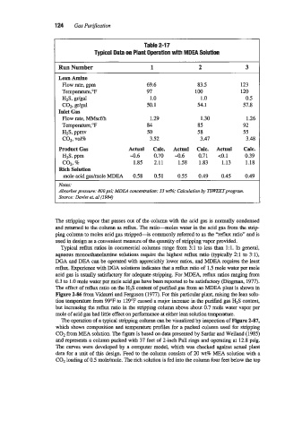
Typical Data on Plant Operation with MDEA Solution
Run Number 1 2 3
Lean Amine
Flow rate, gpm 69.6 83.5 123
Temperature,"F 97 100 120
HzS, 1 .o 1 .o 0.5
CQ, gr/gal 50.1 54.1 57.8
Inlet Gas
Flow rate, h4Mscf/h 1.29 1.30 1.26
Temperature,"F 84 85 92
HzS, ppmv 50 58 55
COZ, vol% 3.52 3.47 3.48
Product Gas Actual Calc. Actual Calc. Actual Calc.
HIS, ppm -0.6 0.70 -0.6 0.71 ~0.1 0.39
coz. 96 1.85 2.11 1.58 1.83 1.13 1.18
Rich Solution
mole acid gadmole MDEA 0.58 0.51 0.55 0.49 0.45 0.49
Notes:
Absorber pressure: 8OOpsi; MDEA concentration: 33 I&?: Calculation by TsWEETprograin.
Source: Daviet et. a1 (1984)
The stripping vapor that passes out of the column with the acid gas is normally condensed
and returned to the column as reflux. The ratio-moles water in the acid gas from the strip-
ping column to moles acid gas stripped-is commonly referred to as the "reflux ratio" and is
used in design as a convenient measure of the quantity of stripping vapor provided.
Typical reflux ratios in commercial columns range from 3:l to less than 1:l. In general,
aqueous monoethanolamine solutions require the highest reflux ratio (typically 2:l to 3:1),
DGA and DEA can be operated with appreciably lower ratios, and MDEA requires the least
reflux. Experience with DGA solutions indicates that a reflux ratio of 1.5 mole water per mole
acid gas is usually satisfactory for adequate stripping. For MDEA, reflux ratios ranging from
0.3 to 1.0 mole water per mole acid gas have been reported to be satisfactory (Dingman, 1977).
The effect of reflux ratio on the H2S content of purified gas from an MDEA plant is shown in
Figure 2436 from Vidaurri and Ferguson (1977). For this particular plant, raising the lean solu-
tion temperam from 99°F to 129°F caused a major increase in the purified gas H2S content,
but increasing the reflux ratio in the stripping column above about 0.7 mole water vapor per
mole of acid gas had little effect on performance at either lean solution temperature.
The operation of a typical stripping column can be visualized by inspection of Figure 2-87,
which shows composition and temperature profiles for a packed column used for stripping
C02 from MEA solution. The figure is based on data presented by Sardar and Weiland (1985)
and represents a column packed with 37 feet of 2-inch Pall rings and operating at 12.8 psig.
The curves were developed by a computer model, which was checked against actual plant
data for a unit of this design. Feed to the column consists of 20 wt% MEA solution with a
C02 loading of 0.5 moldmole. The rich solution is fed into the column four feet below the top