
Page 187 - Geochemical Remote Sensing of The Sub-Surface
P. 187
164 V.T. Jones, M.D. Matthews and D.M. Richers
CHARCOAL TRAP
RADON
IR DETECTOR
Amblerd Air
CO 2 Inlal
-
DUAL GAS RECORDER
CHROMATOGRAPH INTEGRATOR
l~ - C4 Hydrocarbon j
Pneumatic
Valves
& II Flame \\ Carrier
Flame
Ionization II ton o \\ Gas
Detector ~ect r ~ II i PUvl,,~ I! Lxx\'\'\\\'''''~
Support
I,LI 2.1
<
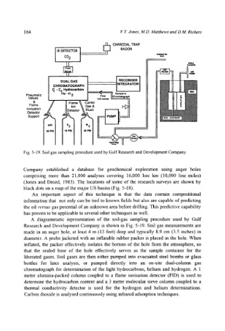
Fig. 5-19. Soil gas sampling procedure used by Gulf Research and Development Company.
Company established a database for geochemical exploration using auger holes
comprising more than 21,000 analyses covering 16,000 line km (10,000 line miles)
(Jones and Drozd, 1983). The locations of some of the research surveys are shown by
black dots on a map of the major US basins (Fig. 5-18).
An important aspect of this technique is that the data contain compositional
information that not only can be tied to known fields but also are capable of predicting
the oil versus gas potential of an unknown area before drilling. This predictive capability
has proven to be applicable to several other techniques as well.
A diagrammatic representation of the soil-gas sampling procedure used by Gulf
Research and Development Company is shown in Fig. 5-19. Soil gas measurements are
made in an auger hole, at least 4 m (13 feet) deep and typically 8.9 cm (3.5 inches) in
diameter. A probe jacketed with an inflatable rubber packer is placed in the hole. When
inflated, the packer effectively isolates the bottom of the hole from the atmosphere, so
that the sealed base of the hole effectively serves as the sample container for the
liberated gases. Soil gases are then either pumped into evacuated steel bombs or glass
bottles for later analysis, or pumped directly into an on-site dual-column gas
chromatograph for determination of the light hydrocarbons, helium and hydrogen. A 1
metre alumina-packed column coupled to a flame ionisation detector (FID) is used to
determine the hydrocarbon content and a 3 metre molecular sieve column coupled to a
thermal conductivity detector is used for the hydrogen and helium determinations.
Carbon dioxide is analysed continuously using infrared adsorption techniques.