
Page 246 - High Power Laser Handbook
P. 246
214 So l i d - S t at e La s e r s Nd:YAG Ceramic ThinZag® High-Power Laser Development 215
−4
1.0
−2 0.5
Position (mm) 0 0.0 Waves (@860 nm)
2 −0.5
−1.0
4
−10 −5 0 5 10
Position (mm)
Figure 9.10 Residual phase-front distortion after the horizontal and vertical
cylinders are removed.
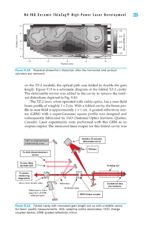
on the TZ-2 module, the optical path was folded to double the gain
length. Figure 9.11 is a schematic diagram of the folded TZ-2 cavity.
The deformable mirror was added to the cavity to remove the resid-
ual distortions depicted in Fig. 9.10.
The TZ-2 laser, when operated with stable optics, has a near-field
beam profile of roughly 1 × 2 cm. With a folded cavity, the beam pro-
file in near field is approximately 1 × 1 cm. A graded reflectivity mir-
ror (GRM) with a super-Gaussian square profile was designed and
subsequently fabricated by INO (National Optics Institute, Quebec,
Canada). Laser experiments were performed with this GRM as an
output coupler. The measured laser output for this folded cavity was
Xinetics 37-actuator
1064-nm alignment and deformable mirror
interferometry probe
Primary
To AOA Shack-Hartmann
sensor
To near-field,
far-field CCD ThinZag cell
To power-
measuring
diagnostics
Mirror on kinematic base Reference Cylindrical lens
pre-corrector
Kinematic base
Telescope to match
expansion of GRM- GRM Output coupler
reflected beam
Figure 9.11 Folded cavity with increased gain length set up with unstable optics
for beam quality measurements. AOA: adaptive optics associates; CCD: charge-
coupled device; GRM: graded reflectivity mirror.