
Page 279 - Hydrogeology Principles and Practice
P. 279
HYDC07 12/5/05 5:32 PM Page 262
262 Chapter Seven
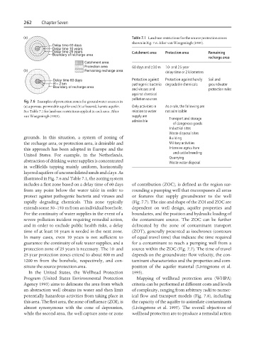
Table 7.1 Land-use restrictions for the source protection zones
shown in Fig. 7.6. After van Waegeningh (1985).
Catchment area Protection area Remaining
recharge area
60 days and ≥30 m 10- and 25-year
delay-time or 2 kilometres
Protection against Protection against hardly Soil and
pathogenic bacteria degradable chemicals groundwater
and viruses and protection rules
against chemical
pollution sources
Fig. 7.6 Examples of protection zones for groundwater sources in
(a) a porous, permeable aquifer and (b) a fissured, karstic aquifer. Only activities in As a rule, the following are
See Table 7.1 for land-use restrictions applied in each area. After relation to water not admissible:
van Waegeningh (1985). supply are Transport and storage
admissible
of dangerous goods
Industrial sites
Waste disposal sites
grounds. In this situation, a system of zoning of Building
the recharge area, or protection area, is desirable and Military activities
this approach has been adopted in Europe and the Intensive agriculture
and cattle breeding
United States. For example, in the Netherlands,
Quarrying
abstraction of drinking water supplies is concentrated Waste water disposal
in wellfields tapping mainly uniform, horizontally
layered aquifers of unconsolidated sands and clays. As
illustrated in Fig. 7.6 and Table 7.1, the zoning system
includes a first zone based on a delay time of 60 days of contribution (ZOC), is defined as the region sur-
from any point below the water table in order to rounding a pumping well that encompasses all areas
protect against pathogenic bacteria and viruses and or features that supply groundwater to the well
rapidly degrading chemicals. This zone typically (Fig. 7.7). The size and shape of the ZOI and ZOC are
extends some 30–150 m from an individual borehole. dependent on well design, aquifer properties and
For the continuity of water supplies in the event of a boundaries, and the position and hydraulic loading of
severe pollution incident requiring remedial action, the contaminant source. The ZOC can be further
and in order to exclude public health risks, a delay delineated by the zone of contaminant transport
time of at least 10 years is needed in the next zone. (ZOT), generally presented as isochrones (contours
In many cases, even 10 years is not sufficient to of equal travel time) that indicate the time required
guarantee the continuity of safe water supplies, and a for a contaminant to reach a pumping well from a
protection zone of 25 years is necessary. The 10- and source within the ZOC (Fig. 7.7). The time of travel
25-year protection zones extend to about 800 m and depends on the groundwater flow velocity, the con-
1200 m from the borehole, respectively, and con- taminant characteristics and the properties and com-
stitute the source protection area. position of the aquifer material (Livingstone et al.
In the United States, the Wellhead Protection 1995).
Program (United States Environmental Protection Mapping of wellhead protection area (WHPA)
Agency 1993) aims to delineate the area from which criteria can be performed at different costs and levels
an abstraction well obtains its water and then limit of complexity, ranging from arbitrary radii to numer-
potentially hazardous activities from taking place in ical flow and transport models (Fig. 7.8), including
this area. The first area, the zone of influence (ZOI), is the capacity of the aquifer to assimilate contaminants
almost synonymous with the cone of depression, (Livingstone et al. 1995). The overall objectives of
while the second area, the well capture zone or zone wellhead protection are to produce a remedial action