
Page 55 - Industrial Cutting of Textile Materials
P. 55
42 Industrial Cutting of Textile Materials
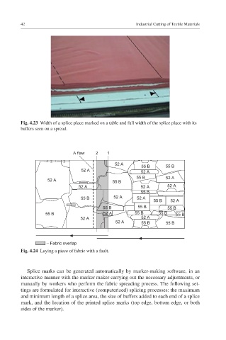
Fig. 4.23 Width of a splice place marked on a table and full width of the splice place with its
buffers seen on a spread.
A flaw 2 1
52 A 55 B 55 B
52 A 52 A
55 B 52 A
52 A 55 B
52 A 52 A 52 A
55 B
55 B 52 A 52 A
55 B 52 A
55 B 55 B 55 B
55 B 52 A 55 B 55 B 55 B
52 A 52 A
52 A 55 B 55 B
– Fabric overlap
Fig. 4.24 Laying a piece of fabric with a fault.
Splice marks can be generated automatically by marker-making software, in an
interactive manner with the marker maker carrying out the necessary adjustments, or
manually by workers who perform the fabric spreading process. The following set-
tings are formulated for interactive (computerized) splicing processes: the maximum
and minimum length of a splice area, the size of buffers added to each end of a splice
mark, and the location of the printed splice marks (top edge, bottom edge, or both
sides of the marker).