
Page 54 - Industrial Cutting of Textile Materials
P. 54
Principles and methods of textile spreading 41
These lines are unlikely to be perfectly straight (there is no exactly straight border
between two parts of a marker). For that reason, two lines are always marked in every
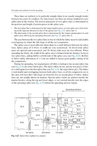
splice area in the marker. The precise placement of two splice lines is determined by
the position and length of pattern pieces in the splice area:
The first splice line is determined by the longest pattern piece in each splice area when look-
●
ing in the opposite direction to that of the spread (see Fig. 4.22, splice line 1).
The placement of the second splice line is determined by the longest pattern piece in each
●
splice area, following the spreading direction (see Fig. 22, splice line 2).
The area between the two splice lines is that in which the fabric must be laid double
(overlapping) to obtain the full shape of all the cut components.
The splice area is most efficient where there is a small distance between the splice
lines. Splice areas of 5–10 cm in width are very economical, 10–20 cm-wide splice
areas are optimal and economical, and 30–40 cm-wide areas are less efficient. When
spreading the fabric, the width of the splice area is formed from the distance between
two splice lines, adding buffers at both ends of the splice area (see Fig. 4.23). Buffers
or fabric safety allowances of 1–2 cm are added to ensure good quality cutting of all
the components.
During the spreading, the original piece of fabric is laid up to the second splice line
(see Fig. 4.24, the lower fabric ply). The fault is then cut out, and the next piece of fab-
ric is laid again from the first splice line (see Fig. 4.24, the upper fabric ply). The fabric
is laid double and overlapping between both splice lines, so all the components cut in
this area will have their full shape cut from the first or second piece of fabric. Splice
lines are not usually shown in markers. Special splice marks are printed outside the
marker borders, along the top and lower edges, or are marked directly onto the edges
of the spreading table (see Fig. 4.23) before the spreading process begins.
Spreading direction
2 1 2 1 2 1
52 A
55 B 55 B
52 A 52 A
55 B
52 A 55 B 52 A
52 A 52 A 52 A
55 B 52 A
55 B 52 A 52 A
55 B 52 A
55 B 52 A 55 B 55 B 55 B
55 B 52 A 55 B 55 B 55 B
52 A 52 A
52 A 55 B 55 B
3rd splice 2nd splice 1st splice
Fig. 4.22 Splice lines marked in a marker.