
Page 161 - Industrial Power Engineering and Applications Handbook
P. 161
Static controls and braking of motors 61141
t t
1
100 100 5
8
=54 54
, I ,, ,
I I I I,
1 ' A '
6 Nr 6 Nr
Speed (in terms of pre-defined bme) + Speed (in terms of pre-defined time) 4
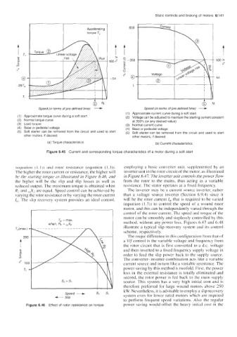
(1) Approximate current curve during a soft start
Approximate torque curve during a soft start (2) Voltage can be adjusted to maintain the starting current constant
Normal torque curve at 350% (or anv desired value)
Load torque (3) Normal current curve
.
I
Base or pedestal voltage (4) Base or pedestal voltage
Soft starter can be removed from the and to start (5) Soft starter can be removed from the circuit and used to start
other motors, if desired. other motors, if desired.
(a) Torque characteristics (b) Current characteristics
Figure 6.45 Current and corresponding torque characteristics of a motor during a soft start
(equation ( 1. I)) and rotor resistance (equation (I 3)). employing a basic converter unit, supplemented by an
The higher the rotor current or resistance, the higher will inverter unit in the rotor circuit of the motor, as illustrated
he the starting torque as illustrated in Figure 6.46, and in Figure 6.47. The inverter unit controls the power flow
the higher will be the slip and slip losses as well as from the rotor to the mains, thus acting as a variable
rcduced output. The maximum torque is obtained when resistance. The stator operates at a fixed frequency.
R3 and ,,X2 are equal. Speed control can be achieved by The inverter may be a current source inverter, rather
varying the rotor resistance or by varying the rotor current than a voltage source inverter (Section 6.9.4) since it
/rl. The slip recovery system provides an ideal control, will be the rotor current tu that is required to be varied
(equation (1.7)) to control the speed of a wound rotor
motor, and this can be independently varied through the
control of the rotor current. The speed and torque of the
I when, R2 = ,,X, I method, without any power loss. Figures 6.47 and 6.48
motor can be smoothly and steplessly controlled by this
Ts, = max.
illustrate a typical slip recovery system and its control
4 t - scheme, respectively.
The major difference in this configuration from that of
a V/fcontrol is the variable voltage and frequency from
the rotor circuit that is first converted to a d.c. voltage
and then inverted to a fixed frequency supply voltage in
order to feed the slip power back to the supply source.
The converter-inverter combination acts like a variable
current source and in turn like a variable resistance. The
power saving by this method is twofold. First, the power
loss in the external resistance is totally eliminated and
second, the rotor power is fed back to the main supply
source. This system has a very high initial cost and is
therefore preferred for large wound motors above 250
Speed - sz si kW. Nevertheless, it is advisable to employ a slip recovery
Slip system even for lower rated motors which are required
to perform frequent speed variations. Also the regular
Figure 6.46 Effect of rotor resistance on torque power saving would offset the heavy initial cost in the