
Page 162 - Industrial Power Engineering and Applications Handbook
P. 162
6/142 Industrial Power Engineering and Applications Handbook
- Main supply - systems, it is now possible to monitor and control a
T - T process line automatically, which would not be feasible
T I if carried out manually. We will consider a simple process
line of a continuous galvanizing plant to demonstrate the
application of this technology in automatic and accurate
control of a process industry.
The total engineering of such a system will first require
a thorough study of the process, dividing this process
into various activities and then monitoring and controlling
each activity through these controls to achieve the required
process operation.
Figure 6.49 illustrates a continuous hot-dip galvanizing
line to perform zinc coating of MS sheets so that the
production line has no discontinuity even when the supply
of sheet is exhausted, or during a changeover from one
feeding route to another or at the finishing line during a
changeover from a completed roll to an empty one. All
this is possible with the use of this technology as described
below.
The process line indicates only the vital areas. There
may be many more auxiliary drives and controls, inter-
connected within the same process line, to adjust the
process and its quality more closely. They have not been
Variable AC voltage DC voltage to shown in the figure for the sake of simplicity. We do not
and frequency fixed frequency discuss the duration of one cycle, its speed, the temperature
converter and voltage
(IGBT or thyristor) supply inverter of the furnace or the hot dip zinc vessel etc. and other
important parameters. These all are a matter of detailed
Figure 6.47 Slip-ring motor control showing slip recovery system engineering and process requirements. We describe the
process only broadly, to give an idea of applying this
first few years only and then provide a recurring energy technology to a process line for very precise control. We
and cost saving. employ encoders to give a pulse output of speed of a
particular drive, and PLCs* to implement the process
6.16.4 Application of solid-state technology in logics through the various drives.
the operation of a process plant
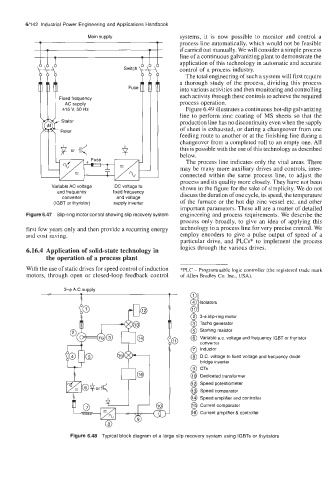
With the use of static drives for speed control of induction *PLC - Programmable logic controller (the registered trade mark
motors, through open or closed-loop feedback control of Allen Bradley Co. Inc., USA).
0
3lsoiators
@ 3-g slip-ring motor
@ Tacho generator
@ Starting resistor
@ Variable ax. voltage and frequency IGBT or thyristor
converter
@ Inductor
@ D.C. voltage to fixed voltage and frequency diode
bridge inverter
@ CTs
@ Dedicated transformer
@ Speed potentiometer
@ Speed comparator
@ Speed amplifier and controller
@ Current comparator
@ Current amplifier & controller
Figure 6.48 Typical block diagram of a large slip recovery system using IGBTs or thyristors