
Page 164 - Industrial Power Engineering and Applications Handbook
P. 164
6/144 Industrial Power Engineering and Applications Handbook
Set
position Tensiometer
( I ,
I l l
I l l
I I l l l l
I l l
I l l
I I I l l l l l l
4 I I ll ll
Tensioi
pits
roll-I roll-2 roll
1 ’-
V
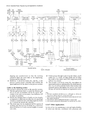
Uncoiler section Process section
@ E - Encoder (Fixed speed and tension)
dipping are synchronized so that the welding 20 It then passes through a pair of guide rollers, pinch
operation takes the same time as the degreasing, rollers no. 5, a shear, an edge guide unit (to align
heating and hot dipping. the width of the sheet) and a final alignment pinch
16 Bridle no. 3, driven by motors MI2 and MI3, is the roll no. 6 as shown.
process section master controller and controls the 21 The recoiler is driven by motor MI-, that adjusts its
speed and travel of the sheet in the process section. speed and tension as calculated for the whole process
line. It is this drive and the bridles that maintain the
Coiler or the finishing section required tension throughout the process and make
This section is almost the same as the uncoiler section. the pay-off reel drives operate as regenerative units.
17 The hot galvanized sheet is cooled by blowers and
fed to an exit accumulator driven by motor MI4, Note
similar to the entry accumulator, via a deflector roll We have considered all drives as a.c. although d.c. drives are
to adjust its position. also in use. Earlier only d.c. drives were used.
18 Before the finished sheet is finally cut into lengths IGBT inverters (the latest in the field of semiconductor devices)
as required or rolled into recoilers its exit speed and have been considered.
All activities can be monitored through a control desk.
tension is monitored and controlled again by bridle All controls and precise adjustments are carried out by a PLC.
no. 4, driven by motors MI5 and MI6
19 The sheet may also be inspected for the quality of 6.16.5 Other applications
welding and checked for pin-holes by a weld-hole
detector before it is finally cut into lengths or wound In view of the low maintenance cost and high reliability
onto rolls. of solid-state devices, combined with precision and