
Page 167 - Industrial Power Engineering and Applications Handbook
P. 167
Static controls and braking of motors 6/147
CT t-w
ASS
Interlocked so that only two
can be made on at a time.
Fuse “i Fuse 0 Fuse 0
sw$
sw$
ASS
CT CTp@
ASS
8 Emergency PB 0 Emergency PB
8 Stop PB 8 Stop PB
I
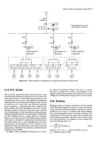
Figure 6.50 Power distribution arrangement for the galvanizing process of Figure 6.49
6.19 D.C. drives d.c. drive we illustrate in Figure 6.51 for a d.c. motor,
the likely variation in its torque, with variation in the
applied voltage, below the base speed and with a constant
The use of d.c. motors for precise speed controls is long voltage but variable field strength, above the base speed.
practised and it had been a unanimous choice until a few
years ago. It still is, in a few applications, purely on cost
considerations. But its use is now gradually waning out 6.20 Braking
in the face of a more advanced technology in static controls
to control an a.c. motor (for very wide and accurate Braking results in heating, irrespective of the method
speed variations, a variable-speed fluid coupling may used. When the braking is external, the heat will appear
not be suitable). But older installations still use d.c. motors in the external circuit and the motor windings will remain
and may continue to do so for a few more years, until the unaffected. But when it is internal, the entire braking
next modernization of the installation, although many heat will be generated within the motor windings. Due
leading manufacturers have discontinued the manufacture consideration of this must be made when selecting the
of such machines due to a sharp decline in demand. motor rating, particularly when the loads are heavy and
There are a few that are still in the field and may continue the braking frequent. An analogue to the starting time
until there is a demand for replacements and extensions
of existing load lines. A few manufacturers who have gives the braking time tb as
discontinued the production of this machine have GD: -N
established links with those still in the field to cater for tb = 7
seconds
(s)
replacements. Therefore this book has not dealt with this 375 Tb
machine in more detail. where N = I?, - Nrl, i.e. speed reduction in r.p.m.
To make a better comparison between an a.c. and a Tb = braking torque in mkg