
Page 172 - Industrial Power Engineering and Applications Handbook
P. 172
6/152 Industrial Power Engineering and Applications Handbook
lowers the load to the ground loading station or the desired
platform, as the situation may require in the event of a power
failure.
The ratings of the brakes noted above are only indicative.
The braking torque of the shoe brakes may diminish with the
number of operations. The heat of braking wears out the brake
linings. The extent of fading will depend upon the braking torque
to decelerate the heavy loads and frequency of its operations.
They may also need replacement of the brake linings, similar to
an automotive vehicle.
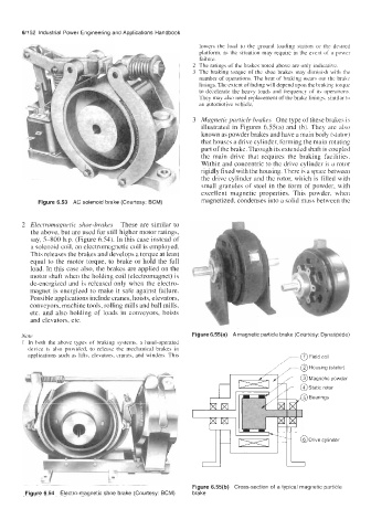
Magnetic particle brakes One type of these brakes is
illustrated in Figures 6.55(a) and (b). They are also
known as powder brakes and have a main body (stator)
that houses a drive cylinder, forming the main rotating
part of the brake. Through its extended shaft is coupled
the main drive that requires the braking facilities.
Within and concentric to the drive cylinder is a rotor
rigidly fixed with the housing. There is a space between
the drive cylinder and the rotor, which is filled with
small granules of steel in the form of powder, with
excellent magnetic properties. This powder, when
Figure 6.53 AC solenoid brake (Courtesy: BCM) magnetized, condenses into a solid mass between the
2 Electromagnetic shoe-brakes These are similar to
the above, but are used for still higher motor ratings,
say, 5-800 h.p. (Figure 6.54). In this case instead of
a solenoid coil, an electromagnetic coil is employed.
This releases the brakes and develops a torque at least
equal to the motor torque, to brake or hold the full
load. In this case also, the brakes are applied on the
motor shaft when the holding coil (electromagnet) is
de-energized and is released only when the electro-
magnet is energized to make it safe against failure.
Possible applications include cranes, hoists, elevators,
conveyors, machine tools, rolling mills and ball mills,
etc. and also holding of loads in conveyors, hoists
and elevators, etc.
Note Figure 6.55(a) A magnetic particle brake (Courtesy: Dynaspede)
1 In both the above types of braking systems, a hand-operated
device is also provided, to release the mechanical brakes in
applications such as lifts, elevators, cranes, and winders. This
*
!-
Figure 6.55(b) Cross-section of a typical magnetic particle
Figure 6.54 Electro-magnetic shoe brake (Courtesy: BCM) brake