
Page 175 - Industrial Power Engineering and Applications Handbook
P. 175
Static controls and braking of motors W155
the windings at the instant of plugging becomes twice (Sl +S2) .*
the rated voltage, and slip as 2S, for the changed Average loss between slip SI and S2 = 2
magnetic field. With these changed parameters, the
current and torque curves can be approximately (i) During a normal running,
determined from equations (1.7a) and (1.3a) res- when S1 = 1 and S2 = 0
pectively, for high slip conditions.
Current and voltage will both give a transitory kick T
at the instant of plugging, depending upon the effective starting heat a starting loss = -
2
voltage across the windings, under the influence of
the motor’s self-induced e.m.f. and the applied voltage. (ii) During plugging,
The transitory state will last only a few cycles and when, S1 = 2 and S2 = 1
then the curves will generally take the shape as in the
equations noted above and illustrated in Figure 6.60. Heat generated during plugging
Generally, except for the initial kick, there will be no
significant variation in the current and torque values
compared to their starting values at S = 1. These values
CM be varied in slipring motors by altering the rotor’s Therefore the heat of the motor during plugging is
circuit resistance. During plug-ging, if the supply is three times that of during a normal start. Stator heat
not switched OFF at the instant of reaching the standstill and thus the total motor heat is a function of the rotor
position, the motor will start rotating in the reverse heat (see also Section 2.7.1). Such a method is therefore
direction, tracing the same speed-torque and speed- not suitable for larger motors or for frequent brakings.
current curves as in the forward direction. But a reverse
direction may damage the driven load. Precautions
are essential to prevent such a situation by providing Note This is an approximate derivation for a simple illustration
an electrical interlock-ing andor a reverse ratchet of the mtio of heats. The time of start and haking is not considered
arrangement in the load coupling. in the above derivation, whereas both would be different and so
will be the heat generated. The time of start would be much
The windings may, however, be subject up to twice higher than the time of braking, as the latter is much higher
the rated voltage and must be suitable to withstand than the former. Figure 6.60 illustrates this. But in view of the
this voltage repeatedly when necessary. The heat gen- high current during plugging the ratio of heat as noted above is
erated during braking will be roughly three times the a near approximation.
heat generated during start-up as determined below:
Rotor losses per phase W = I: . RZ 3 Regenerative braking If the motor be run beyond
synchronous speed by some external means it will
I: . Rz
Rotor torque per phase T = - work as a generator and feed back useful energy to
S the supply system. It will draw only the necessary
excitation current, Im, for the generator action from
W the source of supply. In such a condition, the motor
:. Rotor loss per unit torque - S
=
T
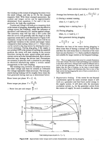
N, 0
C Plugging (braking) -- Running A
Total braking torque at pdnt A = Tt + Tb
Figure 6.80 Approximate motor torque and current characteristic curves during plugging