
Page 174 - Industrial Power Engineering and Applications Handbook
P. 174
6/154 Industrial Power Engtneering and Applications Handbook
the braking torque curve will almost take the shape of for a particular configuration, as indicated in
the motor's normal speed-torque curve. Figure 6.57, To avoid overheating and excessive
If an independent d.c. source is not available a single- electromagnetic forces, i& is normally not
phase transformer and a rectifier bridge as shown in allowed to exceed ZaW)
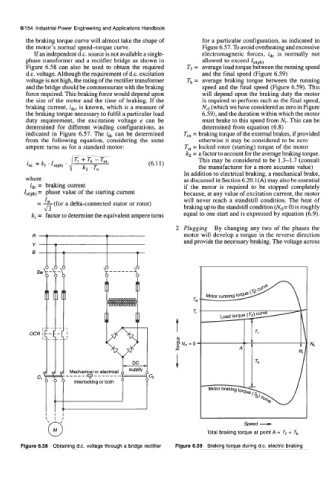
Figure 6.58 can also be used to obtain the required Te = average load torque between the running speed
d.c. voltage. Although the requirement of d.c. excitation and the final speed {Figure 6.59)
voltage is not high, the rating of the rectifier transformex Tb = average braking torque between the running
and the bridge should be commensurate with the braking speed and the final speed (Figure 6.59). This
force required. This braking force would depend upon will depend upon the braking duty the motor
the size of the motor and the time of braking. If the is required to perform such as the final speed,
braking current, idcr is known, which is a measure of Nrl (which we have considered as zero in Figure
the braking torque necessary to fulfil a particular load 6.541, and the duration within which the motor
duty requirement, the excitation voltage e can be must brake to this speed from N,. This can be
determined for different winding configurations, as determined from equation (4.8)
indicated in Figure 6.57. The ik can be determined T, = braking torque of the external brakes, if provided
from the following equation, considering the same otherwise it may be. considered to be zero
ampere turns as for a standard motor: T,, = locked rotor (starting) torque of the motor
ka = a factor to account for the average braking torque.
(4.1 1) This may be considered to be 1.3-1.7 (consult
the manufacturer for a more accurate value)
In addition to electrical br ng, a mechanical brake,
where as discussed in Section 6.20.1(A) may also be essential
z& = braking current if the motor is required to be stopped completely
Ist(phl = phase value of the starting current because, at any value of excitation current, the motor
will never reach a standstill condition, The heat of
= I, (for a delta-connected stator or rotor)
4-3 braking up to the standstill condition {Nrl= 0) is roughly
kl = factor to determine the equivalent ampere turns equal to one start and is expressed by equation (6.9).
2 Plugging By changing any two of the phases the
motor will develop a torque in the reverse direction
and provide the necessary braking. The voltage across
- v
Spsed -
I l l I
$ 1 8
Totel braking torque at point A = Te + Tb
Figure 6.58 Obtaining d.c. voltage through a bridge rectifier Figure 6.59 Braking torque during d.c. electric braking