
Page 177 - Industrial Power Engineering and Applications Handbook
P. 177
Static controls and braking of motors 611 57
Motor output he negative slip) the higher will be the stator current and
(generator input by the generator will run overloaded. To safeguard against
overloading, relays or similar protections must be provided
Motoring in the supply lines to disconnect the motor beyond a
region specific speed (generally beyond the rated negative slip).
after a certain time delay, if such a situation arises.
In downhill conveyors, running mostly on stored
potential energy by gravity, the motor may overspeed
-Motor's no-load line B, beyond excessive limits unless prevented by a brake or a
Dl Generator output line - D tachogenerator relay.
0
P.
Critical speed
At certain speeds, rotating masses become dynamically
unstable and cause deflection and vibration in the rotor
which may damage the motor. The speed at which such
instability occurs is known as critical speed and occurs
at different multiples of the rated speed. The m
must therefore rotate within 20% below or above the
critical speeds to avoid such a situation. These vibrations
Figure 6.62 Circle diagram for an induction generator settle down again at higher speeds above critical and
recur at the next higher critical speed.
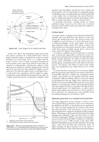
Figure 6.63 shows the generating region and torque To achieve a vibration level of 0 micron in a rotating
and current variation for a dual-speed motor when at mass is practically impossible. It will possess some run-
higher speed the supply is changed over to the low-speed out, however precisely and accurately it has been balanced.
winding. From the torque curve it is evident that the While rotating, therefore, the shaft on which the other
torque reverses twice in quick succession through two masses rotate, will deflect to the side which is heavier
reverse peaks (curve area nbcd) and the motor must be and the opacity around the centre of the shaft will become
suitable to withstand this. All the parts, subject to this uneven. The masses will rotate in small circles about
phenomenon should be carefully designed and selected their own geometrical axis rather than the axis of the
and rotor bars and end rings should be tightly secured shaft.
and braced. Precautions against heavy centrifugal forces In a motor the first critical speed is several times higher
to which the rotor conductors will be subject at super- than the operating speed and may not reach in operation.
synchronous speed should also be taken into account. At In downhill conveyors, without any mechanical speed
a higher speed beyond the synchronous (a higher rated control, such speeds may be reached when the motor
overspeeds while descending. When so, the motor should
be disconnected from the supply lines, otherwise there
will be excessive overloading. There may be several critical
speeds in a rotating mass which tend to become infinite
with the number of loads on the same shaft. But the first
critical speed alone is of significance, as other critical
speeds much higher than even the first critical speed are
of no relevance. No rotating mass may possibly reach
this during operation in an induction motor.
Induction generator as a wind-powered generator
The main application of this machine is found in non-
conventional energy generation, such as for wind power,
gas turbines and mini- or microhydro power generation
etc. They are used extensively to convert wind power
into electrical power, The wind power is Pirat converted
into rotating kinetic energy by aerodynamically designed
blades. This energy is then converted into electrical energy
I 1 1 through these machines. They are thus known as wind
0 1000 electricity generators (WEC). Presently such machincs
Speed (r.p.m.) + Fti,l 500 are in use from 50 kW to 6 MW worldwide. In India they
I, - Motoring current drawn from the source are in use for up to I MW (mostly in the range 400-
/G - Generating or braking, current fed to the source 600 kW). Potential locations for such machines are coastal
areas, whcrc thcre are high and continuous winds. In
Figure 6.63 Motoring and generating torque curves for a
1500/1000 r p.m. dual-speed motor (torque and current curves India examples of these locations are in the states of
for generating region are drawn for only low-speed winding) Maharashtra, Kerala, Tamil Nadu, Karnataka and GLi.jarat.