
Page 173 - Industrial Power Engineering and Applications Handbook
P. 173
Static controls and braking of motors W153
drive cylinder and the rotor and provides the required
braking effect. This is possible with the help of a
magnetic field which is provided through a stationary
magnetic coil placed in the main housing outside the
pexiphery of the drive cylinder as shown. The field
strength of this coil can be varied with the help of a
variable current source to obtain a variable braking
torque and thus achieve more precise braking control,
even remotely. Depending upon the type of application
and accuracy of the speed control desired, extremely
precise and accurate electronic controls are available.
These can infinitely vary the torque and hence the
speed of the motor. Such braking devices are available
in the range 0.1 kW-60 kW.
Strength of brakes
The brakes should be suitable to counter at least the
torque developed by the motor. They must therefore 0 25 50 75 100
develop at least this amount of torque. To find the least %Speed---,
braking torque, the brake drums must be able to develop,
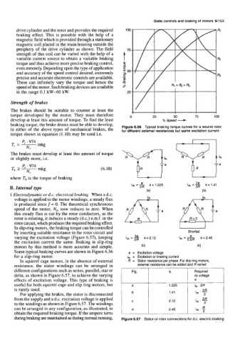
in either of the above types of mechanical brakes, the Figure 6.56 Typical braking torque curves for a wound rotor
for different external resistances but Same excitation current
torque shown in equation (1.10) may be used i.e.
The brakes must develop at least this amount of torque
or slightly more, i.e.
(6.10)
where Tb is the torque of braking
B. Internal type
1 Electrodynamic or d.c. electrical braking When a d.c.
voltage is applied to the motor windings, a steady flux
is produced since f = 0. The theoretical synchronous
speed of the motor, N,, now reduces to zero. When
this steady flux is cut by the rotor conductors, as the
rotor is rotating, it induces a steady (d.c.) e.m.f. in the
rotor circuit, which produces the required braking effect. u
In slip-ring motors, the braking torque can be controlled
by inserting suitable resistance in the rotor circuit and Shorted
varying the excitation voltage (Figure 6.57), keeping
the excitation current the same. Braking in slip-ring
motors by this method is more accurate and simple.
Some typical braking curves are shown in Figure 6.56 e = Excitationvoltage
for a slip-ring motor. .& = Excitation or braking current
In squirrel cage motors, in the absence of external R = Stator resistance per phase. For slip-ring motors,
resistance, the stator windings can be arranged in external resistance can be added and R varied
different configurations such as series, parallel, star or Fig. k Required
delta, as shown in Figure 6.57, to achieve the varying dc voltage
effects of excitation voltage. This type of braking is e
useful for both squirrel cage and slip ring motors, but a 1.225 i&. 2R
is rarely used. idc . -
3R
For applying the brakes, the stator is disconnected b 1.41 2
from the supply and a d.c. excitation voltage is applied
to the windings as shown in Figure 6.57. The windings
R
.
can be arranged in any configuration, as illustrated, to d 2.45 I& ' -
obtain the required braking torque. If the ampere turns 2
during braking are maintained as during normal running, Figure 6.57 Stator or rotor connections for d.c. electric braking