
Page 178 - Industrial Power Engineering and Applications Handbook
P. 178
6/158 Industrial Power Engineering and Applications Handbook
The electricity generated depends primarily on the speed Mean wind speed = 25 kmph
of the wind at the site of installation. A conventional
formula to determine the wind energy, based on the design - 25 x 1000 m,s
of the rotor (rotating blades) and the site conditions is - 60 x 60
given by = 6.94 rn!~
P = 0.5 . C, . A * p . V3* (6.13)
Note Generally, the ratio of rated to mean wind speed may be
where quite high due to long lean periods, when the machine may stay
P = power generated by the turbine (windmill) in watts idle. reducing the value of the mean speed.
Cp = coefficient of performance which depends upon
the aerodynamic efficiency of the rotor and varies Shutdown speed = 20 mls
with the number of blades and their profile. This Rotor diameter including hub = 39.35 m
factor is provided by the mill supplier and generally Rotational speed of the rotor at the rated wind speed
varies between 0.35 and 0.45 = 38 r.p.m.
A = swept area of the rotor in m2
KO2
-- Example 6.5
For the above machine the wind power considering the C,as
- 4 0.35 will be:
where
39.35’ 11.53
D = diameter of the rotor (blades) in m P = 0.5 x 0.35 x 1.225 x x x -
p = air density = 1.225 kg/cm3 4
V = velocity of wind at the site of installation, at the = 396.3 kW
height of the hub in mls
* The ideal condition would be when the rotor output Below we give a brief idea of the mechanical system of
is a cubic function of wind speed. But in practice such a mill and its various controls, as a passing reference.
this may not be so. It is found to be linear or a For more details on the subject, see the Further reading
near quadratic (square) function of the wind speed, at the end of the chapter.
as shown in Figure 6.64
Mechanical system
Typical specification for a KEC (India) 400 kW machine
is provided below for a general reference: See Figure 6.65, illustrating the general arrangement of
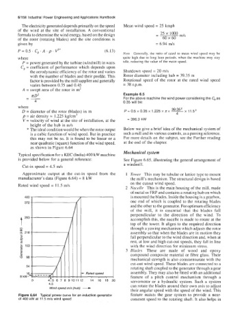
Cut-in speed = 4.5 mls a windmill.
Approximate output at the cut-in speed from the I Tower This may be tubular or lattice type to mount
manufacturer’s data (Figure 6.64) = 8 kW the mill’s mechanism. The structural design is based
on the cutout wind speed.
Rated wind speed = 11.5 m/s
2 Nacelle This is the main housing of the mill, made
of metal or FRP and contains a rotating hub on which
is mounted the blades. Inside the housing is a gearbox,
one end of which is coupled to the rotating blades
and the other to the generator. For optimum efficiency
of the mill, it is essential that the blades fall
perpendicular to the direction of the wind. To
accomplish this, the nacelle is made to rotate at the
top of the tower. It aligns to the required direction
through a yawing mechanism which adjusts the rotor
assembly so that when the blades are in motion they
fall perpendicular to the wind direction and, when at
rest, at low and high cut-out speeds, they fall in line
with the wind direction for minimum stress.
3 Blades These are made of wood and epoxy
compound composite material or fibre glass. Their
mechanical strength is also commensurate with the
cut-out wind speed. These blades are connected to a
rotating shaft coupled to the generator through a gear
, - Ratedspeed assembly. They may also be fitted with an additional
Wind speed m/s (hub) - servomotor or a hydraulic system. Such a system
feature of a pitch control mechanism through a
0 415 6 7 8 9 1011 12 14 16 18 20
4.5 can rotate the blades around their own axis to adjust
their angular speed with the speed of the wind. This
Figure 6.64 Typical power curve for an induction generator feature assists the gear system to provide a near-
of 400 kW at 11.5 m/s wind speed constant speed to the rotating shaft. It also helps in