
Page 176 - Industrial Power Engineering and Applications Handbook
P. 176
6/156 industrial Power Engineering and Applications Handbook
will exert a countertorque, the magnitude of which
will depend upon the motor speed above synchronous.
Such braking conditions may occur automatically in
downhill conveyors, lifts and hoists etc. while
descending with the load, i.e. operating as an induction
motor while ascending and as an induction generator
while descending. The generator and the braking action
ceases at synchronous speed. For speed control below Jr
synchronous speed, therefore, it will be essential to
employ a multi-speed motor which, at a higher speed, 0
can be switched to the lower speed winding to make
the motor work as a generator between the high and
the low speeds. Such a braking method, however, has BJ
QF
only limited commercial applications, as in a sugar 52
centrifuge motor (Section 7.4).
With the application of solid-state technology,
however, as discussed above, the potential energy of
the loads in hoists, lifts and conveyors during descents
can be saved and fed back to the source.
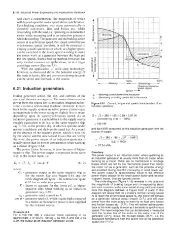
0 100% 200%
Motoring Speed -
Generating
6.21 Induction generators (Super synchronous
speed region)
During generator action, the slip, and currents of the /M - Motoring current drawn from the source
stator and the rotor are negative. The motor draws reactive IC - Generating or braking current fed to the source
power from the source for its excitation (magnetization) Figure 6.61 Current, torque and speed characteristics of an
since it is not a self-excited machine. However, it feeds induction generator
back to the supply system an active power almost equal
in magnitude to the motor rating or slightly less or more,
depending upon its supersynchronous speed. As an G = 43 x 380 x 185 x 0.89 x 0.97 w
induction generator, it can feed back to the supply source (considering r~ as = 100%)
roughly equivalent to its h.p. at the same negative slip, = 105 kW
say, 3-5%, as the positive slip, at which it operates under
normal conditions and delivers its rated h.p. As a result and the kVAR consumed by the induction generator from the
of the absence of the reactive power, which is now fed source of supply,
-
by the source and the mechanical losses that are fed by I & x 380 x 185 x 4
the wind, the power output of an induction generator is -
usually more than its power consumption when working 0.97 x 1000
as a motor (Figure 6.61). = 57.24 kVAr
The power factor, however, is poor because of higher
negative slip. The power output is expressed in the same Corollary
way as the motor input, i.e. The power output of an induction motor, when operating as
an induction generator, is usually more than its output when
working as a motor. There are no mechanical or windage
GI = J~.I,.V.COS$.K (6.12) losses which are fed by the mechanical power that makes
the motor run as a generator, such as the potential energy
where accumulated during downhill conveying or wind power etc.
GI = generator output at the same negative slip as The power output is approximately equal to the effective
for the motor. See also Figure 6.61 and the power intake except for the lower power factor and resistive
circle diagram of Figure 1.16, redrawn in Figure (copper) losses, that are ignored above.
6.62 for an induction generator The circle diagram (Figure 1.16) reverses in this case and
K = factor to account for the lower p.f. at higher the magnitude of braking torque and corresponding stator
and rotor currents can be ascertained at any particular speed
negative slips when working as an induction from this diagram redrawn in Figure 6.62. A study of this
generator (say, 0.97). diagram will reveal that for a motor’s normal running speed
IG = generator rated current in A. N, to reach the synchronous speed Ns, the motor will behave
cos Q = generator rated p.f. which is quite high compared as a generator without output (region DIPl) and will draw
to a motor, as the reactive power is now supplied power from the main supply to meet its no-load core losses
by the external source. and friction losses etc. (DIPl). This will deliver active power
back to the main supply as soon as it exceeds its synchronous
speed. The maximum power that can be delivered is measured
Example 6.4 from the no-load line of the motor to the output line of the
For a 100 kW, 380 V induction motor operating at an generator (DlP2) minus the no-load losses (DIP,), i.e. the
approximate r~ of 92.2%, having I, as 185 A and cos @ as downward hemisphere from the centre line or the generator
0.89, the output as an induction generator will be output line (PlP2).