
Page 159 - Industrial Power Engineering and Applications Handbook
P. 159
Static controls and braking of motors 61139
6.44. Varying the firing angle and the applied voltage
1 25
will also affect the dynamic phase balancing in each
Hd2 1 138 phase, and controls the I,, and T,, as programmed.
-Rated Increasing the firing angle decreases the angle of
point conduction and causes the voltage to decrease. as seen in
t Hd‘ O0
--. Figure 6.23. The starting voltage, i.e. the angle of firing,
is pre-set according to the minimum voltage required, to
$ 075 ensure a permissible minimum T,, and maximum I,, which
2
P can be predetermined with the help of the motor
characteristics and the load requirements. The voltage is
050
Hd3 0 45 raised to full, gradually and smoothly, but within a pre-
set time, as determined by the motor and the load
characteristics. The size of the static starter will depend
0 25 upon the starting current chosen and the corresponding
starting time. Generally, the normal practice of the various
1 I manufacturers, as noted earlier, is to define the size of
I 1 Qi
0- their soft starters, based on a starting current of I SO% of
025 050 067075
1,and a starting time of up to one minute. A higher starting
current or a higher duration of start may call for a larger
starter. The starter therefore provides no control over the
starting current, which is a function of the applied voltage.
It is also possible to perform a cyclic duty having
some no load or a light load and some fully loaded periods,
as discussed in Section 3.3. The firing angles of the
SCRs or the triacs can also be programmed accordingly
to reduce the applied voltage to the motor to a minimum
Speed -c-
possible level, during no-load or light-load periods, and
Hd - Head Q - Discharge hence conserving on otherwise wasted energy by saving
H, - Rated head Qn - Rated discharge on the no-load losses. Different mathematical algorithms
N - Actual speed q - Pump efficiency are used to achieve the desired periodic T-Ncharacteristics
N, - Rated speed of the machine.
During start-up, the firing angle is kept high to keep
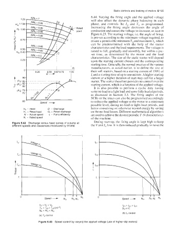
Figure 6.42 Discharge versus head curves of a pump at
different speeds and resistances introduced by throttle the V and I,, low. It is then reduced gradually to raise the
(b) control
Figure 6.43 Speed control by varying the applied voltage (use of higher-slip motors)