
Page 394 - Instrumentation Reference Book 3E
P. 394
Common electrochemical analyzers 377
unit through the sample flow control valve and
up the metering tube into the head control block
where reagent (buffer solution to maintain con-
stant pH) is added by means of a positive dis-
placement feed pump.
Buffered sample flows down tube B, through
the flow control block and up tube C to the
bottom of the electrode cell assembly. Sample
flow rate is adjusted to approximately 150 milli-
liters per :minute. Flow rate is not critical since the
relative velocity between the measuring electrode
and the sample is established by rotating the
electrode at high speed. fill port
In the electrode cell assembly, the sample
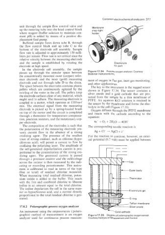
passes up through the annular space between Figure 17.34 Processoxygen analyzer. Courtesy
Beckman Instruments Inc.
the concentrically mounted outer (copper) refer-
ence electrode and the inner (gold) measuring ment of oxygen in flue gas, inert gas monitoring.
electrode and out through tube D to the drain. and other applications.
The space between the electrodes contains plastic The key to the instrument is the rugged sensor
pellets which are continuously agitated by the shown in Figure 17.34. The sensor contains a
swirling of the water in the cell. The pellets keep silver anode and a gold cathode that are pro-
the electrode surfaces clear of any material, which tected from the sample by a thin membrane of
might tend to adhere. The measuring electrode is PTFE. An aqueous KC1 solution is retained in
coupled to a motor, which operates at 1550 rev/ the sensor by the membrane and forms the elec-
min. The electrical signal from the measuring trolyte in the cell (Figure 17.35).
electrode is picked up by a spring-loaded brush Oxygen diffuses through the PTFE membrane
on top of the motor and the circuit is completed and reacts with the cathode according to the
through a thermistor for temperature compensa- equation:
tion, precision resistors, and the instationary cop-
per electrode. 4e- + 02 + 2H20 --f 40H
The composition of the electrodes is such that The corresponding anodic reaction is
the polarization of the measuring electrode pre-
vents current flow in the absence of a strong Ag + C1- i AgCl + e-
oxidizing agent. The presence of the smallest For the reaction to continue, however, an exter-
trace of strong oxidizer, such as chlorine (hypo- nal potential (0.7 volt) must be applied between
chlorous acid), will permit a current to flow by
oxidizing the polarizing layer. The amplitude of --
the self-penerated depolarization current is pro-
portional to the concentration of the strong oxi-
dizing agent. The generated current is passed
through a precision resistor and the millivoltage
across the resistor is then measured by the indi-
cating or recording potentiometer. This instru-
ment is calibrated to read in terms of the type -Outer body
(free or total) of residual chlorine measured.
When measuring total residual chlorine, potas-
sium iodide is added to the buffer. This reacts
with the free and combined chlorine to liberate
iodine in an amount equal to the total chlorine.
The iodine depolarizes the cell in the same man-
ner as hypo~hlorous acid, and a current directly
proportional to the total residual chlorine is gen-
erated.
Teflon membrane
1'7.8.2 Polarographic process oxygen analyzer
An instrument using the amperometric ( polaro- Gold cathode
graphic) method of measurement is an oxygen Figure 17.35 Diagram of polarographic oxygen sensor.
analyzer used for continuous process measure- Courtesy Institute of Measurement and Control.