
Page 392 - Instrumentation Reference Book 3E
P. 392
Potentiometry and specific ion measurement 375
-1 1
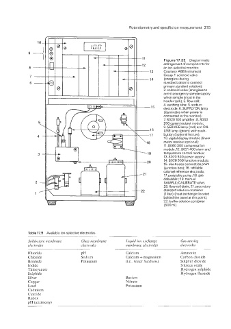
Figure 17.32 Diagrammatic
-12 arrangement of componentsfor
an ion-selective monitor.
13 Courtesy ABB Instrument
Group. 1. solenoid valve
14 (energizes during
standardization to connect
primary standard solution);
2. solenoid valve (energizes to
admit emergency sample supply
when sample is lost in the
header tank); 3. flow cell:
4. earthing tube; 5. sodium
electrode; 6. SUPPLY ON lamp
(illuminates when power is
connected to the monitor):
7. 8020 100 amplifier; 8.8033
200 current output moduie;
9. SERVICE lamp (red) and ON-
LINE lamp (green) with push-
button (optional feature);
10. digital display module (linear
motor readout optional):
11.8060 300 compensation
module;l2. 8021 400 alarm and
temperature control module;
13.8020 500 power supply;
14.8020 600 function module;
15. electrodes connection point
(junction box); 16. refillable
calomel reference electrode;
17. peristaltic pump; 18. gas
debubbler; 19. manual
SAMPLE/CALIBRATE valve;
20. flow cell drain; 21. secondary
standard solution container
(1 liter) (heat exchanger located
behind the panel at this point):
22. buffer solution container
(500 ml)
Table 17.9 Avaiiable ion-selective electrodes
Solid-state membrane Glass membrane Liquid ion exchange Gus-sensing
electrodes electrodes membrane electrodes electrodes
Fluoride PH Calcium Ammonia
Chloride Sodium Calcium + magnesium Carbon dioxide
Bromide Potassium (is.: water hardness) Sulphur dioxide
Iodide Nitrous oxide
Thiocyanate Hydrogen sulphide
Sulphide Hydrogen fluoride
Silver Barium
Copper Nitrate
Lead Potassium
Cadmium
Cyanide
Redox
pH (antimony)