
Page 570 - Instrumentation Reference Book 3E
P. 570
552 Measurements employing nuclear techniques
emitted by the substance when irradiated with X- The intensity thus received will be proportional to
rays is determined by means of a dispersive X-ray cos 6’ and to dQ. After dividing by cos 0 and cor-
spectrometer, which uses as its analyzing element recting for the variation with angle of the reflec-
the regular structure of a crystal through which tion coefficient of the crystal and the variation
the characteristic X-rays are passed. This prop- with wavelength of the detector efficiency, the
erty was discovered by Bragg and Bragg in 1913, recorded signal will be proportional to the inten-
who produced the first X-ray spectrum by crystal sity per unit wavelength interval, and it is in this
diffraction through a crystal of rock salt. form that continuous X-ray spectra are tradition-
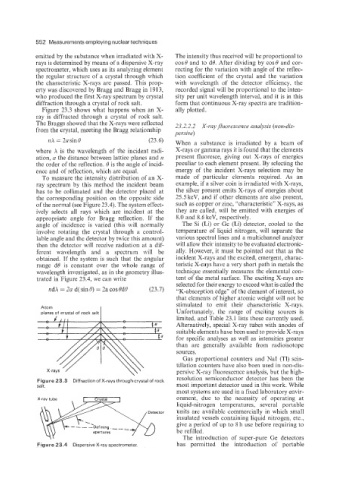
Figure 23.3 shows what happens when an X- ally plotted.
ray is diffracted through a crystal of rock salt.
The Braggs showed that the X-rays were reflected 23.2.2.2 X-rayJluovt.sceizce analysis (non-dis-
from the crystal, meeting the Bragg relationship y evsive)
1zX = 2a sin 6’ (23.6) When a substance is irradiated by a beam of
where X is the wavelength of the incident radi- X-rays or gamma rays it is found that the elements
ation, a the distance between lattice planes and IZ present fluoresce, giving out X-rays of energies
the order of the reflection. 6’ is the angle of incid- peculiar to each element present. By selecting the
ence and of reflection, which are equal. energy of the incident X-rays selection may be
To measure the intensity distribution of an X- made of particular elements required. As an
ray spectrum by this method the incident beam example. if a silver coin is irradiated with X-rays,
has to be collimated and the detector placed at the silver present emits X-rays of energies about
the corresponding position on the opposite side 25.5 keV, and if other elements are also present,
of the normal (see Figure 23.4). The system effect- such as copper or zinc, “characteristic” X-rays, as
ively selects all rays which are incident at the they are called. will be emitted with energies of
appropriate angle for Bragg reflection. If the 8.0 and 8.6 keV, respectively.
angle of incidence is varied (this will normally The Si (Li) or Ge (Li) detector, cooled to the
involve rotating the crystal through a control- temperature of liquid nitrogen, will separate the
lable angle and the detector by twice this amount) various spectral lines and a multichannel analyzer
then the detector will receive radiation at a dif- will allow their intensity to be evaluated electronic-
ferent wavelength and a spectrum will be ally. However, it must be pointed out that as the
obtained. If the system is such that the angular incident X-rays and the excited, emergent, charac-
range d6’ is constant over the whole range of teristic X-rays have a very short path in metals the
wavelength investigated, as in the geometry illus- technique essentially nieasures the elemental con-
trated in Figure 23.4, we can write tent of the metal surface. The exciting X-rays are
selected for their energy to exceed what is called the
iidX = 2a d( sin 6’) = 2a cos 0d6’ (23.7) “K-absorption edge” of the element of interest, so
that elements of higher atomic weight will not be
stimulated to emit their characteristic X-rays.
Atom
Unfortunately, the range of exciting sources is
limited, and Table 23.1 lists those currently used.
Alternatively, special X-ray tubes with anodes of
suitable elements have been used to provide X-rays
for specific analyses as well as intensities greater
than are generally available from radioisotope
sources.
Gas proportional counters and NaI (Tl) scin-
tillation counters have also been used in non-dis-
persive X-ray fluorescence analysis, but the high-
resolution semiconductor detector has been the
Figure 23.3 Diffraction of X-rays through crystal of rock
salt. most important detector used in this work. While
most systems are used in a fixed laboratory envir-
X-ray tube onment, due to the necessity of operating at
liquid-nitrogen temperatures, several portable
Detector units are available commercially in which small
insulated vessels containing liquid nitrogen, etc.,
give a period of up to 8 h use before requiring to
apertures be refilled.
The introduction of super-pure Ge detectors
Figure 23.4 Dispersive X-ray spectrometer. has permitted the introduction of portable