
Page 573 - Instrumentation Reference Book 3E
P. 573
Materials analysis 555
1.0 -
t.
0.5 1.0 1.5 2.0 2.5 3.0
Soil density (g/crn3)
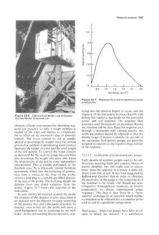
Figure 23.7 Response of a scattered-gamma-ray gauge
to soil densitv.
tering into the detector begins to occur, and the
response of the instrument increases linearly with
Figure 23.6 Coke moisture gauge in use on hoppers density but reaches a maximum for the particular
Courtesy Nuclear Enterprises Ltd.
source and soil material. The response then
decreases until theoretically at maximum density
elements of large cross-section for absorbing neu- the response will be zero. Since the response goes
trons are present), so only a rough estimate is through a maximum with varying density, the
needed of the total soil density to compensate
for its effect on the measured value of moisture probe parameters should be adjusted so that the
density range of interest is entirely on one side of
content. The water content in soil is usually the maximum. Soil-density gauges are generally
quoted as percentage by weight, since the normal
gravimetric method of determining water content designed to operate on the negative-slope portion
measures the weight of water and the total weight of the response.
of the soil sample. To convert the water content
as measured by the neutron gauge measurement 23.2.3.1 Calibration of neutron-moistlire gauges
into percentage by weight one must also know
the total density of the soil by some independent Early models of neutron gauges used to be cali-
measurement. This is usually performed, in the brated by inserting them into concrete blocks of
borehole case, by a physically similar borehole known densities, but this could lead to serious
instrument, which uses the scattering of gamma- error, since the response in concrete is quite dif-
rays from a source in the nose of the probe, ferent from that in soil. It has been suggested by
around a lead plug to a suitable gas-filled detector Ballard and Gardner that in order to eliminate
the sensitivity of the gauge to the composition of
in the rear of the probe. The lead plug shields the
detector from any direct radiation from the the material to be tested, one should use non-
compactive homogeneous materials of known
source. Figure 23.7 shows the response of the
instrument. composition to obtain experimental gauge
responses. This data is then fitted by a “least-
At zero density of material around the probe
the response of the detector is zero, since there is squares” technique to an equation which enables
a correction to be obtained for a particular probe
no material near the detector to cause scattering used in soil of a particular composition.
of the gamma rays and subsequent detection. In
practice, even in free air, the probe will show a
small background due to scattering by air mol- Dual guuges Improved gauges have been devel-
ecules. As the surrounding density increases, scat- oped in which the detector is a scintillation