
Page 178 - Integrated Wireless Propagation Models
P. 178
156 C h a p t e r T h r e e
3 . 1 . 8. 1 Coverage Files5
A file stores the predicted path loss values along each radial for a given set of elevation,
terrain, and model parameters. Whenever possible, files are shared across sectors and
tiers at a single geolocation to save disk space and file calculation time. When antenna
heights or model parameters differ between co-located sectors/tiers, the additional
final files are created.
A coverage file has two components:
1. A header containing various identification fields, including the format version,
date and time stamp, prediction area extents, parameter values used, and the
number of points along each radial.
2. Path loss values stored in n arrays of p values, where n is the number of radials
used in the calculation and p is the number of elements along each of the radi
als. Note that p = (radial distance/radial distance unit) + 1 .
a
a
The time required for calculating a coverage file s well s the file size are deter
mined by three calculation parameters as follows:
1. The radial distance (from 1 to 100 miles), which can be specified by the
individual user on a sector-by-sector basis
2. The number of radials (either 360, 720, 1440, or 2880), which can be specified by
the individual user on a sector-by-sector basis
3. The distance between points along the radial (radial distance unit)
3.1.8.2 RSSI Grid Files
An RSSI (Received Signal Strength Indicator) file stores the received signal strength
value (in dBm) for each bin in the predicted area. An RSSI file is the result of the conver
sion of a radial-based coverage file into a grid-based block of values for a given bin size.
Several options and formats of the stored final file values can be used to provide an
aligned sample space for the different tiers involved.
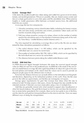
Note that the distance between arc seconds differs in the latitudinal and longitudi
nal directions, depending on the latitudinal position on the earth. Thus, the bin sizes
given in the table are approximate, and the bins are rectangular, not square.
Storage space requirements for grid files increase four times when bin size is
reduced in half. To help conserve disk space, choose the largest bin size suitable for the
intended analysis. If desired, you may create plots using a size of multiple bins.
Grid files are generally created only when needed to support data visualization or
other bin-based analyses. The grid file is based on the bin size and does the interpreta
tion to attain better granularity. For example, there can be four grids in one of the bins,
and the data for each grid are interpreted based on the data in each bin. There are many
different ways of doing the interpretation.
Arc sec 24 12 6 3 1.5 0.75 0.375 0 . 1 875
Meters 720 360 180 90 45 22.5 11.25 5 . 625
Feet 2400 1200 600 300 150 75.0 37.5 18.75
TABLE 3.1.8.2.1 Sample of Supported Bin Sizes