
Page 229 - Integrated Wireless Propagation Models
P. 229
M i c r o c e l l P r e d i c t i o n M o d e l s 207
4.2.3.2 The Non-LOS Situation
Now focusing on the losses due to building loss, we need to eliminate the terrain effects.
To do this, we need to have a building layout of the area under consideration.
Figure 4.2.2.1 . 1 shows a sample building's layout, which is in the standard AutoCAD
DXF file format. The prediction tool is developed for the analysis of the model and
takes the vector-based building data as the input. In reality, the buildings are not on a
flat surface, but so that we can accurately find the effect of the building losses on the
received signal, we consider the surface to be flat. The model currently is based on 2D
building data. There is no consideration of the height of the building; rather, the thick
ness of the building is the main phenomenon for predicting the losses.
The detailed explanation of the loss due to building blocks has been discussed. •
1 6
The blocking is caused by the thickness of buildings B a , Bv and Be and their respective
c
radial cutting thickness being a, b, and a s shown in Sec. 4.2. . 2. The blockage L8 can be
1
expressed as
(4.2.3.2.1)
where P ws = LOS signal and P d = the signal received after passing the building blocks
bl
(the measured local means).
4.2.4 The Terrain Effect
4.2.4. 1 Nonshadow Region
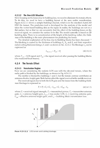
Now we are considering the realistic LOS case with the elevated terrain, where the
1
radio path is blocked by the buildings, as shown in Fig. 4.2.4. . 1 .
b
i
2
The mobile s blocked y buildings 1 and , but the terrain contour contributes an
antenna effective height gain. Both factors affect the signal received at the mobile receiver.
The received signal due to both the LOS gain and the losses from the building thick
ness blockage is expressed as
(4.2.4.1.1)
where P, = received signal strength, P1 = transmitted power, G1 = transmitter antenna
gain, G a = antenna height gain, L ws = loss under LOS, G, = receiving antenna gain,
G = effective antenna height gain, and L8 = b uilding block transmission loss.
,1fl,
FIGURE 4.2.4.1.1 LOS terrain and building blockage.