
Page 166 - Introduction to Computational Fluid Dynamics
P. 166
P1: IWV
0521853265c05
5.6 APPLICATIONS
5.0 CB908/Date 0 521 85326 5 5.0 May 20, 2005 12:28 145
Re
Re = 24800 25000
4.0 4.0
51500
50000
3.0 3.0
100000 Nu fd
/ 100000
Nu
2.0 2.0
1.0 1.0
EXPT DATA Pr = 3 PREDICTIONS Pr = 3
0.0 0.0
0 5 10 15 0 5 10 15
X/D X/D
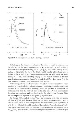
Figure 5.17. Sudden expansion, with R 2 /R 1 = 2 and q w = constant.
In both cases, the domain downstream of the orifice or nozzle is considered. At
2
the inlet section, the specifications are u in = 4 × u, e in = (0.1 × u in ) , and in is
2
evaluated from the specification µ t /µ = C µ ρ e / in = 0.003 Re for 0 ≤ r < R 1
in
and u in = 0 (wall) for R 1 ≤ r ≤ R 2 . The Reynolds number of the larger pipe is
defined as Re = ρ u 2 R 2 /µ. Computations are carried out with ρ = 1 and u = 1
and R 2 = 1. Thus, Re is varied by varying µ. The Nusselt numbers at different
axial locations are evaluated from Nu x = q w 2 R 2 /K (T w − T b ), where T b is the
bulk temperature and T w is the wall temperature at each x.
In the computations, 67 (streamwise) × 28 (radial) nodes were used with closer
spacings in the recirculation region to accurately predict the point of reattachment.
Because of the close near-wall spacings, it was not possible to ensure that the
first node away from the wall will have sufficiently large y at all axial stations.
+
Therefore, the two-layer wall function is active for velocity (see Equation 5.86).
For the temperature equation, PF is given by Equation 5.88.
In Figure 5.17, predicted Nu x /Nu fd are compared with the experimen-
tal data of Krall and Sparrow. Here, as per their recommendation, Nu fd =
0.0123 Re 0.874 Pr 0.4 . In these computations, the reattachment point is predicted at
x/(2 R 2 ) ≈ 1.84 at all Reynolds numbers. The predicted Nu max locations (≈1.81)
thus appear to coincide with the point of flow reattachment. The high values of
Nu max /Nu fd indicate that the recirculation region is by no means dead with respect